STM32–Firmware Architecture part1:开发环境和HAL API应用 STM32–开发环境 当前主流的几种方案:(软件免费,无法律风险):
1.STM32CubeMX + Keil(社区版)+ VSCode:使用CubeMX快速创建工程并导出为MDK-ARM项目文件,使用Keil编译调试MDK-ARM项目包,使用VSCode编辑代码和版本管理。
优势:兼容老项目,资料最多;Keil的调试经验可以复用到其他非STM32 ARM芯片;
https://www.keil.arm.com/mdk-community/
https://www.st.com/en/development-tools/stm32cubemx.html
2.STM32CubeIDE:ST主推的方式,专用于ST32芯片的IDE,本质是STM32CubeMX + Eclipse IDE + ST的编译调试工具链。
优势:集成度最高;缺陷:只用于STM32
https://www.st.com/en/development-tools/stm32cubeide.html#overview
3.VSCode + ARM/ST插件 + GDB + OpenOCD + + STM32CubeMX
优势:通用性最强,对各类ARM/RISCV等SOC都适用此方案。
缺陷:资料少,GDB debug效率没有Keil高。
https://stm32world.com/wiki/STM32_development_and_debugging_using_VSCode
结论:对于生产环境的STM32开发还是首选方案1,Keil社区版的功能和付费版基本一致。
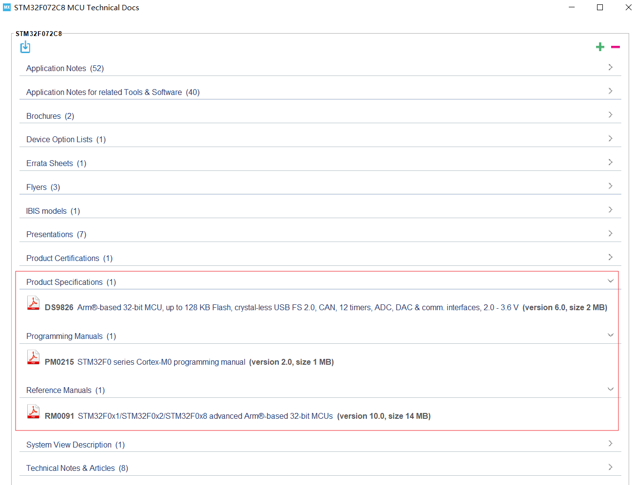
STM32–必读手册和固件 STM32开发手册 helps->docs & resource, 下载F0系列的:
Data Sheet(DS), Reference Manual(RM), Programming Manual(PM).
此外还有F1系列才有的User Manual UM1850 ,里面详细介绍各外设Driver的设计标准和API如何使用,对F0的Firmware也是通用,去ST官网下载。
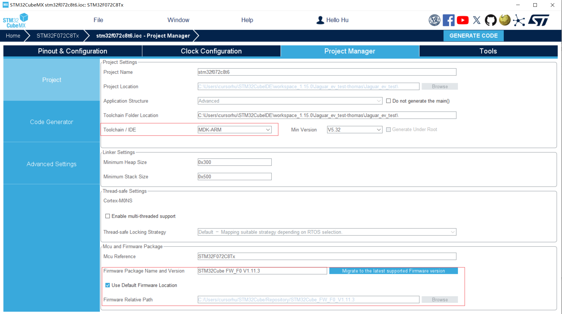
STM32固件包 CubeMX/CubeMXIDE首次运行STM32工程会要求安装STM32FXX的固件包,路径:CubeMX工程管理页面 -> Firmware Package Path
原厂固件包的作用:
1.固件包是MCU厂商提供,学习任何一种MCU应该首先参考原厂固件包,不然容易被第三方教程误导。
2.对于STM32CubeMX, 其创建工程的原理是从固件包拷贝现成的模板代码,再根据用户在GUI界面配置的外设功能参数,自动输出项目代码。这个操作类似于VisualStudio开发MFC/WinForm GUI应用,GUI模块被自动生成C#代码。
对于STM32F072xb的固件包,重点关注:
1.固件说明文档:STM32Cube\Repository\STM32Cube_FW_F0_V1.11.4\Documentation\STM32CubeF0GettingStarted.pdf
2.模板代码和示例代码:STM32Cube\Repository\STM32Cube_FW_F0_V1.11.4\Projects\STM32072B_EVAL\Examples
3.User Manual:整个固件库的代码文档,一般用HAL库关键词索引完整API定义
STM32Cube\Repository\STM32Cube_FW_F0_V1.11.4\Drivers\STM32F0xx_HAL_Driver\STM32F072xB_User_Manual.chm
小结:STM32项目的代码架构 根据开发手册和固件包文档做个小结。
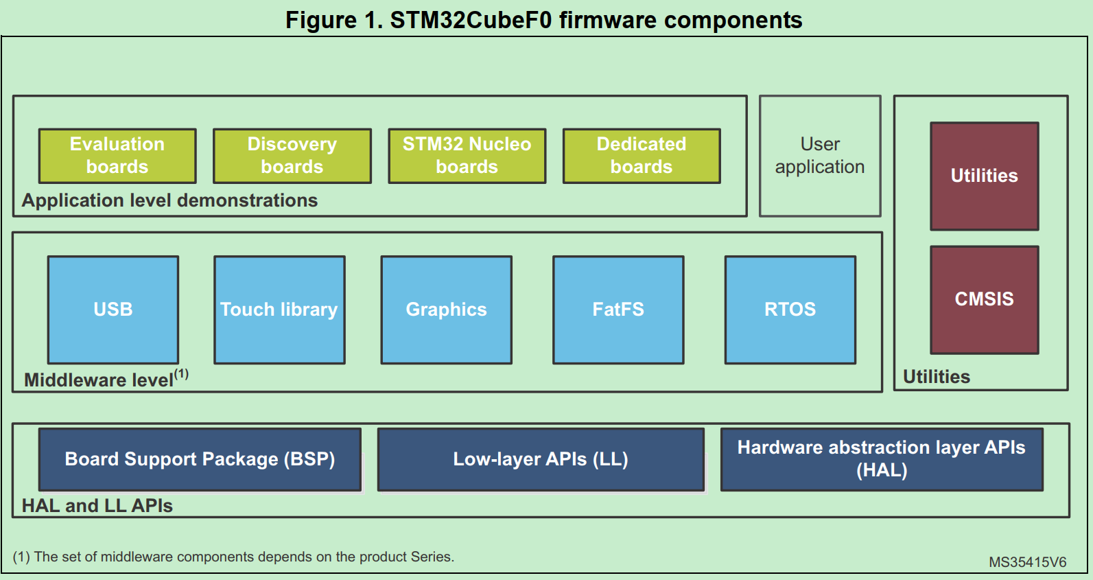
STM32固件的架构,这也是STM32 Firmware项目的基本架构:
HAL和LL APIs是ST提供的STM32 chipset API,目的是hide theMCU and peripheral complexity to end user
区别:
HAL drivers offer high-level and function-oriented APIs, with a high level of portability. Product/IPs complexity is hidden for end users.
LL drivers offer low-layer APIs at registers level, with a better optimization but less portability. They require a deep knowledge of product/IPs specifications.
HAL可以理解为硬件协议层,不直接配置register level,只实现通信协议和硬件配置流程。
LL是register level,完全不涉及通信协议和设备流程性的配置。
SysTick interrupts 只能在HAL使用,LL API无法调用SysTick interrupts,因为SysTick实际上是Hardware Timer的应用,而不是操作timer本身。
CMSIS(Cortex Microcontroller Software Interface Standard) ARM指定的Cortex-M 硬件抽象层标准
Middleware:相当于应用层的基础库。The middleware is a set of libraries covering USB Device Libraries, STMTouch touch sensing, STemWin, FreeRTOS and FatFS
STM32–编译过程 对于嵌入式代码的分析,首先应该看Makefile,去总览项目结构和编译过程。
以下有两种编译生态:
Keil style:在Keil中编译MDK-ARM工程,编译过程被Keil隐藏到项目配置中;
Makefile style:CubeMX将MDK-ARM工程输出为Makefile工程,能一次看清整个编译过程。
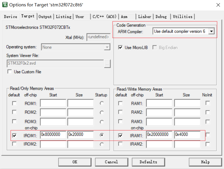
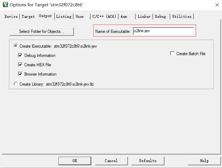
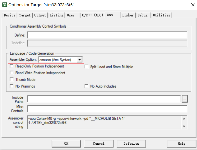
Keil style Keil编译配置 指定ARM编译器,指定代码目标是RAM\Flash位置的基地址
指定输出文件
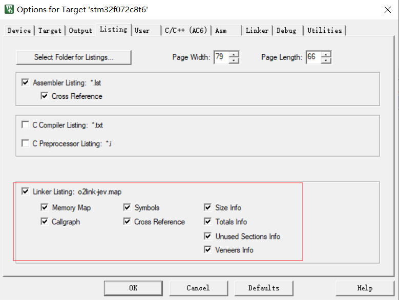
链接输出的符号总览文件.map
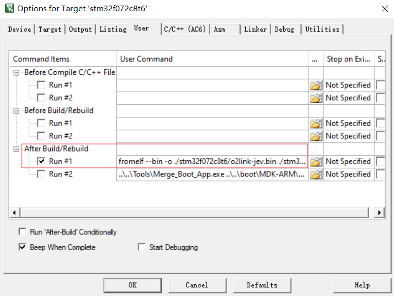
编译的后处理过程,从hex生产bin
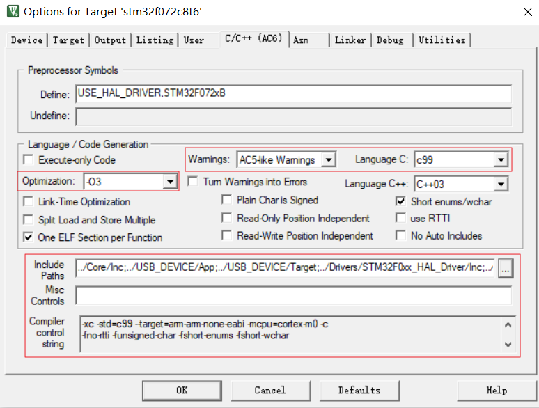
指定代码优化级别,警告级别,语言标准;指定头文件,组合成编译参数
指定汇编器,一些伪汇编符号语法(syntax)和汇编器类型相关,例如Arm syntax和GUN syntax有很大差异
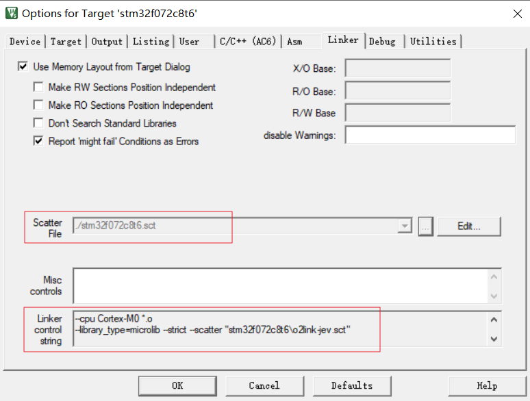
指定链接文件(scatter file), 功能对应Makefile的.ld链接脚本文件,用于指定各段分布。
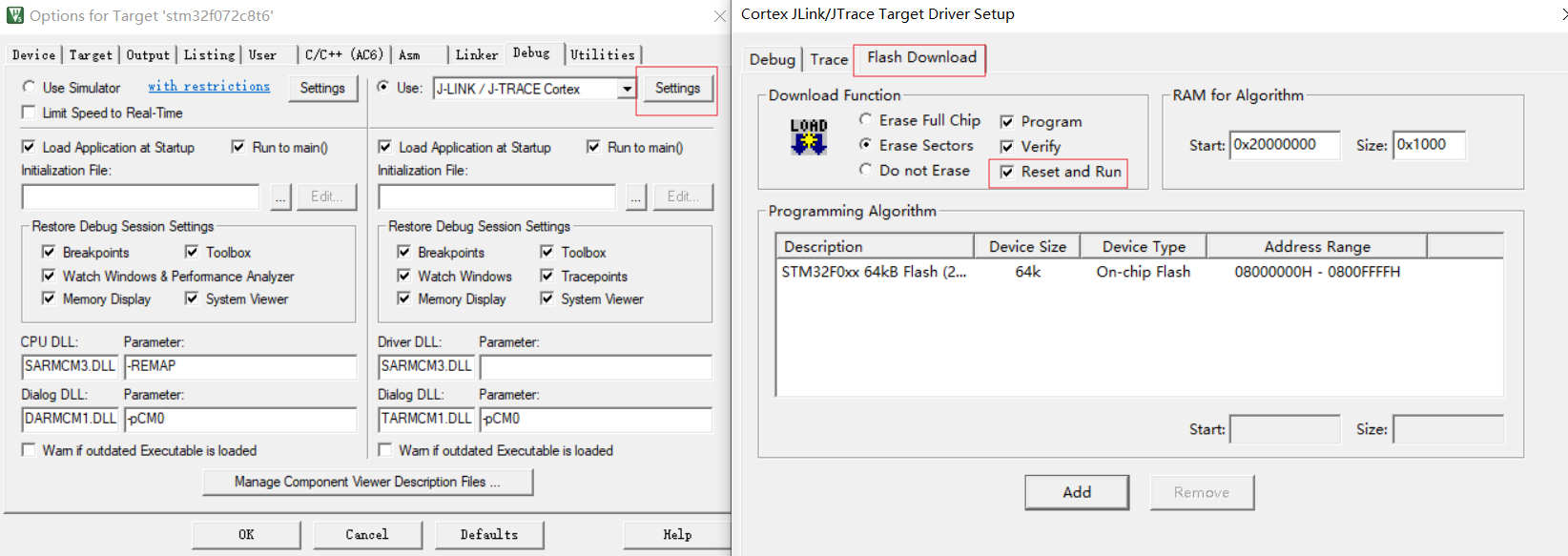
Debug和JLink烧录的配置,这里勾选JLink烧录后自动reset启动新程序:
这里实际是Keil调用JFlash烧写,需要指定Flash地址和大小,一般和Keil项目配置的ROM区间一致
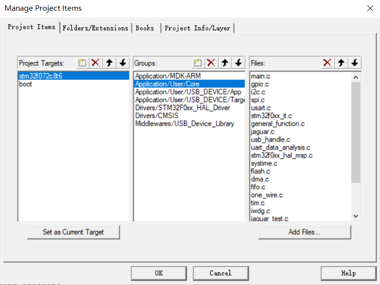
项目的目录配置中指定哪些.c参与编译:
Keil链接配置 Keil的链接脚本是.sct文件,链接配置的主要作用是在对.o文件链接时,指定链接基础地址,指定排列顺序。
1
2
3
4
5
6
7
8
9
10
11
12
LR_IROM1 0x08000000 0x00020000 { ; load region size_region ER_IROM1 0x08000000 0x00020000 { ; load address = execution address *.o (RESET, +First) *(InRoot$$Sections) .ANY (+RO) .ANY (+XO) } RW_IRAM1 0x20000000 0x00004000 { ; RW data .ANY (+RW +ZI) } }
有两个比较重要的概念:
加载域与执行域
LR: Load Address,MCU从哪个空间加载代码
ER:Execute Address,MCU在哪个空间执行代码
以上STM32链接脚本,所有Flash的代码(IROM: *.o, RO, XO)的执行域和加载域都是Flash(0x08000000 ~ 0x00020000),且指定bootloader entry:RESET为最开始执行的函数。
RAM的代码(IRAM: RW, ZI)加载域是SRAM,这部分是数据是运行时直接在RAM初始化,不需要从Flash取指令。
下图示例是执行Flash的RO data时,RW数据段(有初始值的数据)应该被bootloader拷贝到RAM。
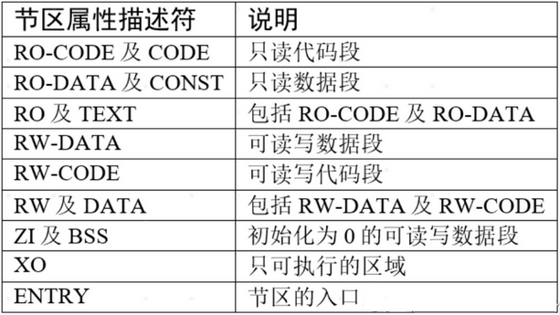
代码段,数据段,BSS段…
STM32的代码段分布如下表, 其中CODE(包括RO/RW CODE和TEXT),DATA(RO/RW DATA),ZI(BSS) 即常规意义的可执行程序的三段。
在.sct链接脚本中对应:RO,RW和ZI(zero initialized )
参考:【STM32】sct 分散加载文件的格式与应用
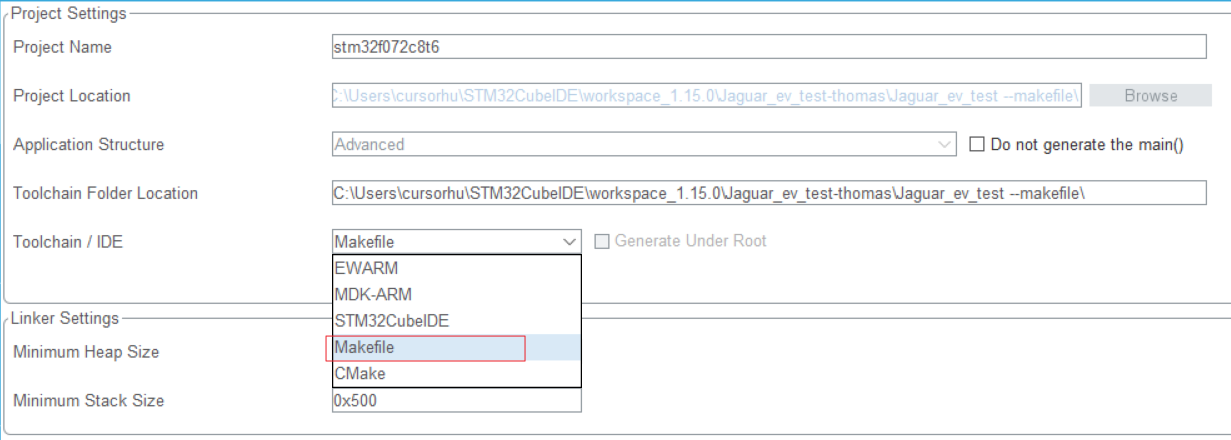
Makefile style makefile编译配置 将已有的CubeMX+MDK工程输出为Makefile工程,产生Makefile和STM32F072C8Tx_FLASH.ld文件.
Makefile分析:
指定编译目标,debug和优化级别
1
2
3
4
5
6
# target TARGET = stm32f072c8t6 # debug build? DEBUG = 1 # optimization OPT = -Og
指定参与编译的源码.c和.s
1
2
3
4
5
6
7
8
9
10
11
12
13
14
15
16
17
18
19
20
21
22
23
# C sources C_SOURCES = \ Core/Src/main.c \ Core/Src/gpio.c \ Core/Src/can.c \ Core/Src/i2c.c \ Core/Src/spi.c \ Core/Src/usart.c \ Core/Src/stm32f0xx_it.c \ Core/Src/stm32f0xx_hal_msp.c \ .... Core/Src/system_stm32f0xx.c \ Middlewares/ST/STM32_USB_Device_Library/Core/Src/usbd_core.c \ Middlewares/ST/STM32_USB_Device_Library/Core/Src/usbd_ctlreq.c \ Middlewares/ST/STM32_USB_Device_Library/Core/Src/usbd_ioreq.c \ Middlewares/ST/STM32_USB_Device_Library/Class/CustomHID/Src/usbd_customhid.c \ Core/Src/sysmem.c \ Core/Src/syscalls.c # ASM sources ASM_SOURCES = \ startup_stm32f072xb.s
指定目标平台的编译器和链接器,指定输出hex/bin
1
2
3
4
5
6
7
8
9
PREFIX = arm-none-eabi- CC = $(PREFIX)gcc AS = $(PREFIX)gcc -x assembler-with-cpp CP = $(PREFIX)objcopy SZ = $(PREFIX)size HEX = $(CP) -O ihex BIN = $(CP) -O binary -S
编译参数CFLAGS和ASFLAGS
1
2
3
CPU = -mcpu=cortex-m0 # float-abi MCU = $(CPU) -mthumb $(FPU) $(FLOAT-ABI)
宏定义和头文件
1
2
3
4
5
6
7
8
9
10
11
12
13
14
15
16
17
18
19
20
21
22
23
# macros for gcc # AS defines AS_DEFS = # C defines C_DEFS = \ -DUSE_HAL_DRIVER \ -DSTM32F072xB # AS includes AS_INCLUDES = # C includes C_INCLUDES = \ -ICore/Inc \ -IUSB_DEVICE/App \ -IUSB_DEVICE/Target \ -IDrivers/STM32F0xx_HAL_Driver/Inc \ -IDrivers/STM32F0xx_HAL_Driver/Inc/Legacy \ -IMiddlewares/ST/STM32_USB_Device_Library/Core/Inc \ -IMiddlewares/ST/STM32_USB_Device_Library/Class/CustomHID/Inc \ -IDrivers/CMSIS/Device/ST/STM32F0xx/Include \ -IDrivers/CMSIS/Include
最终的完整GCC FLAGS
1
2
3
4
# compile gcc flags ASFLAGS = $(MCU) $(AS_DEFS) $(AS_INCLUDES) $(OPT) -Wall -fdata-sections -ffunction-sections CFLAGS += $(MCU) $(C_DEFS) $(C_INCLUDES) $(OPT) -Wall -fdata-sections -ffunction-sections
链接脚本与库路径
1
2
3
4
5
6
7
# link script LDSCRIPT = STM32F072C8Tx_FLASH.ld # libraries LIBS = -lc -lm -lnosys LIBDIR = LDFLAGS = $(MCU) -specs=nano.specs -T$(LDSCRIPT) $(LIBDIR) $(LIBS) -Wl,-Map=$(BUILD_DIR)/$(TARGET).map,--cref -Wl,--gc-sections
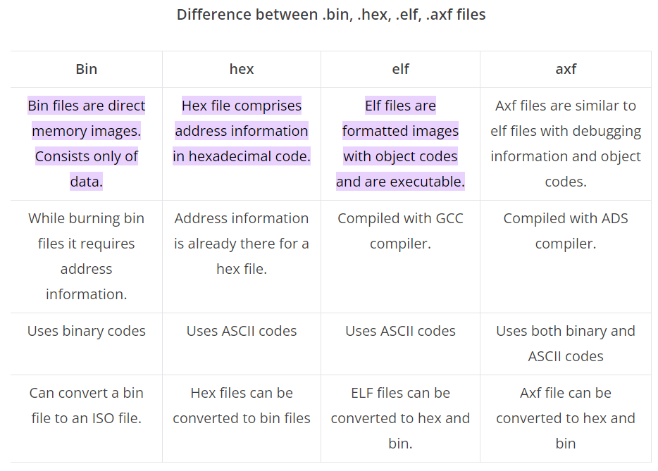
输出文件:elf + hex + bin,参考:[elf,hex,bin,axf的区别](# elf,hex,bin,axf的区别)
1
2
# default action: build all all: $(BUILD_DIR)/$(TARGET).elf $(BUILD_DIR)/$(TARGET).hex $(BUILD_DIR)/$(TARGET).bin
编译执行部分:
1
2
3
4
5
6
7
8
9
10
11
12
13
14
15
16
17
18
19
20
21
22
23
24
25
26
27
28
29
# list of objects OBJECTS = $(addprefix $(BUILD_DIR)/,$(notdir $(C_SOURCES:.c=.o))) vpath %.c $(sort $(dir $(C_SOURCES))) # list of ASM program objects OBJECTS += $(addprefix $(BUILD_DIR)/,$(notdir $(ASM_SOURCES:.s=.o))) vpath %.s $(sort $(dir $(ASM_SOURCES))) OBJECTS += $(addprefix $(BUILD_DIR)/,$(notdir $(ASMM_SOURCES:.S=.o))) vpath %.S $(sort $(dir $(ASMM_SOURCES))) $(BUILD_DIR)/%.o: %.c Makefile | $(BUILD_DIR) $(CC) -c $(CFLAGS) -Wa,-a,-ad,-alms=$(BUILD_DIR)/$(notdir $(<:.c=.lst)) $< -o $@ $(BUILD_DIR)/%.o: %.s Makefile | $(BUILD_DIR) $(AS) -c $(CFLAGS) $< -o $@ $(BUILD_DIR)/%.o: %.S Makefile | $(BUILD_DIR) $(AS) -c $(CFLAGS) $< -o $@ $(BUILD_DIR)/$(TARGET).elf: $(OBJECTS) Makefile $(CC) $(OBJECTS) $(LDFLAGS) -o $@ $(SZ) $@ $(BUILD_DIR)/%.hex: $(BUILD_DIR)/%.elf | $(BUILD_DIR) $(HEX) $< $@ $(BUILD_DIR)/%.bin: $(BUILD_DIR)/%.elf | $(BUILD_DIR) $(BIN) $< $@ $(BUILD_DIR): mkdir $@
清理编译输出:
1
2
clean: -rm -fR $(BUILD_DIR)
makefile链接配置 GNU linker(LD)的语法参考:GNU linker ld (GNU Binutils)
STM32F072C8Tx_FLASH.ld:
1
2
3
4
5
6
7
8
9
10
11
12
13
14
15
16
17
18
19
20
21
22
23
24
25
26
27
28
29
30
31
32
33
34
35
36
37
38
39
40
41
42
43
44
45
46
47
48
49
50
51
52
53
54
55
56
57
58
59
60
61
62
63
64
65
66
67
68
69
70
71
72
73
74
75
76
77
78
79
80
81
82
83
84
85
86
87
88
89
90
91
92
93
94
95
96
97
98
99
100
101
102
103
104
105
106
107
108
109
110
111
112
113
114
115
116
117
118
119
120
121
122
123
124
/* Entry Point */ ENTRY(Reset_Handler) /* Highest address of the user mode stack */ _estack = ORIGIN(RAM) + LENGTH(RAM); /* end of RAM */ /* Generate a link error if heap and stack don't fit into RAM */ _Min_Heap_Size = 0x300; /* required amount of heap */ _Min_Stack_Size = 0x500; /* required amount of stack */ /* Specify the memory areas */ MEMORY { RAM (xrw) : ORIGIN = 0x20000000, LENGTH = 16K FLASH (rx) : ORIGIN = 0x8000000, LENGTH = 64K } /* Define output sections */ SECTIONS { /* The startup code goes first into FLASH */ .isr_vector : { . = ALIGN(4); KEEP(*(.isr_vector)) /* Startup code */ . = ALIGN(4); } >FLASH /* The program code and other data goes into FLASH */ .text : { . = ALIGN(4); *(.text) /* .text sections (code) */ *(.text*) /* .text* sections (code) */ *(.glue_7) /* glue arm to thumb code */ *(.glue_7t) /* glue thumb to arm code */ *(.eh_frame) KEEP (*(.init)) KEEP (*(.fini)) . = ALIGN(4); _etext = .; /* define a global symbols at end of code */ } >FLASH /* Constant data goes into FLASH */ .rodata : { . = ALIGN(4); *(.rodata) /* .rodata sections (constants, strings, etc.) */ *(.rodata*) /* .rodata* sections (constants, strings, etc.) */ . = ALIGN(4); } >FLASH .ARM.extab : { *(.ARM.extab* .gnu.linkonce.armextab.*) } >FLASH .ARM : { __exidx_start = .; *(.ARM.exidx*) __exidx_end = .; } >FLASH .preinit_array : { PROVIDE_HIDDEN (__preinit_array_start = .); KEEP (*(.preinit_array*)) PROVIDE_HIDDEN (__preinit_array_end = .); } >FLASH .init_array : { PROVIDE_HIDDEN (__init_array_start = .); KEEP (*(SORT(.init_array.*))) KEEP (*(.init_array*)) PROVIDE_HIDDEN (__init_array_end = .); } >FLASH .fini_array : { PROVIDE_HIDDEN (__fini_array_start = .); KEEP (*(SORT(.fini_array.*))) KEEP (*(.fini_array*)) PROVIDE_HIDDEN (__fini_array_end = .); } >FLASH /* used by the startup to initialize data */ _sidata = LOADADDR(.data); /* Initialized data sections goes into RAM, load LMA copy after code */ .data : { . = ALIGN(4); _sdata = .; /* create a global symbol at data start */ *(.data) /* .data sections */ *(.data*) /* .data* sections */ . = ALIGN(4); _edata = .; /* define a global symbol at data end */ } >RAM AT> FLASH /* Uninitialized data section */ . = ALIGN(4); .bss : { /* This is used by the startup in order to initialize the .bss secion */ _sbss = .; /* define a global symbol at bss start */ __bss_start__ = _sbss; *(.bss) *(.bss*) *(COMMON) . = ALIGN(4); _ebss = .; /* define a global symbol at bss end */ __bss_end__ = _ebss; } >RAM /* User_heap_stack section, used to check that there is enough RAM left */ ._user_heap_stack : { . = ALIGN(8); PROVIDE ( end = . ); PROVIDE ( _end = . ); . = . + _Min_Heap_Size; . = . + _Min_Stack_Size; . = ALIGN(8); } >RAM
编译输出: elf,hex,bin,axf的区别
链接输出的.map符号表 链接过程可以输出.map符号表,可用于分析代码和数据分布,再裁剪代码。
ROM(Flash)的.hex/bin文件的符号分布:
可以看到,.sct指定的首个符号RESET在最开始位置,其他符号是链接器自动排列
1
2
3
4
5
6
7
8
9
10
11
12
13
14
15
16
17
18
19
20
21
22
23
24
25
26
27
28
29
30
31
32
33
============================================================================== Memory Map of the image Image Entry point : 0x080000c1 Load Region LR_IROM1 (Base: 0x08000000, Size: 0x000082f0, Max: 0x00020000, ABSOLUTE, COMPRESSED[0x00008148]) Execution Region ER_IROM1 (Exec base: 0x08000000, Load base: 0x08000000, Size: 0x00007f84, Max: 0x00020000, ABSOLUTE) Exec Addr Load Addr Size Type Attr Idx E Section Name Object 0x08000000 0x08000000 0x000000c0 Data RO 3 RESET startup_stm32f072xb.o 0x080000c0 0x080000c0 0x00000000 Code RO 2440 * .ARM.Collect$$$$00000000 mc_p.l(entry.o) 0x080000c0 0x080000c0 0x00000004 Code RO 2728 .ARM.Collect$$$$00000001 mc_p.l(entry2.o) 0x080000c4 0x080000c4 0x00000004 Code RO 2731 .ARM.Collect$$$$00000004 .... mc_p.l(init.o) 0x08000244 0x08000244 0x00000020 Code RO 2768 .text mc_p.l(llshl.o) 0x08000264 0x08000264 0x00000056 Code RO 2784 .text mc_p.l(__dczerorl2.o) 0x080002ba 0x080002ba 0x00000002 PAD 0x080002bc 0x080002bc 0x00000064 Code RO 769 .text.CDC_Control_FS usbd_cdc_if.o 0x08000320 0x08000320 0x00000004 Code RO 767 .text.CDC_DeInit_FS usbd_cdc_if.o 0x08000324 0x08000324 0x00000024 Code RO 765 .text.CDC_Init_FS usbd_cdc_if.o 0x08000348 0x08000348 0x00000034 Code RO 771 .text.CDC_Receive_FS usbd_cdc_if.o 0x0800037c 0x0800037c 0x00000044 Code RO 773 .text.CDC_Transmit_FS usbd_cdc_if.o 0x080003c0 0x080003c0 0x00000010 Code RO 136 .text.CEC_CAN_IRQHandler stm32f0xx_it.o 0x080003d0 0x080003d0 0x00000004 Code RO 750 .text.CUSTOM_HID_DeInit_FS usbd_custom_hid_if.o 0x080003d4 0x080003d4 0x00000004 Code RO 748 .text.CUSTOM_HID_Init_FS usbd_custom_hid_if.o ....
RAM中的数据段分布,包括.data段和.bss段:
可以看到,有初始值和无初始值的全局变量分布在.data和.bss区域。
1
2
3
4
5
6
7
8
9
10
11
12
13
14
15
16
17
18
19
20
21
22
23
24
25
26
27
28
29
30
31
32
33
34
35
36
37
38
39
40
41
42
43
44
45
46
47
48
Execution Region RW_IRAM1 (Exec base: 0x20000000, Load base: 0x08007f88, Size: 0x000021b8, Max: 0x00004000, ABSOLUTE, COMPRESSED[0x000001c0]) Exec Addr Load Addr Size Type Attr Idx E Section Name Object 0x20000000 COMPRESSED 0x00000004 Data RW 2742 .data mc_p.l(stdout.o) 0x20000004 COMPRESSED 0x00000008 Data RW 1117 .data..L_MergedGlobals stm32f0xx_hal.o 0x2000000c COMPRESSED 0x00000022 Data RW 754 .data.CUSTOM_HID_ReportDesc_FS usbd_custom_hid_if.o 0x2000002e COMPRESSED 0x00000002 PAD 0x20000030 COMPRESSED 0x0000001c Data RW 733 .data.FS_Desc usbd_desc.o 0x2000004c COMPRESSED 0x00000004 Data RW 2228 .data.SystemCoreClock system_stm32f0xx.o 0x20000050 COMPRESSED 0x00000038 Data RW 2427 .data.USBD_CDC usbd_cdc.o 0x20000088 COMPRESSED 0x00000043 Data RW 2429 .data.USBD_CDC_CfgFSDesc usbd_cdc.o 0x200000cb COMPRESSED 0x00000001 PAD 0x200000cc COMPRESSED 0x00000043 Data RW 2428 .data.USBD_CDC_CfgHSDesc usbd_cdc.o 0x2000010f COMPRESSED 0x00000001 PAD 0x20000110 COMPRESSED 0x0000000a Data RW 2431 .data.USBD_CDC_DeviceQualifierDesc usbd_cdc.o 0x2000011a COMPRESSED 0x00000002 PAD 0x2000011c COMPRESSED 0x00000010 Data RW 775 .data.USBD_CDC_Interface_fops_FS usbd_cdc_if.o 0x2000012c COMPRESSED 0x00000008 Data RW 776 .data.USBD_CDC_LineCoding usbd_cdc_if.o 0x20000134 COMPRESSED 0x00000043 Data RW 2430 .data.USBD_CDC_OtherSpeedCfgDesc usbd_cdc.o .... 0x20000368 - 0x0000002c Zero RW 29 .bss..L_MergedGlobals main.o 0x20000394 - 0x00000030 Zero RW 287 .bss..L_MergedGlobals systime.o 0x200003c4 - 0x00000024 Zero RW 569 .bss..L_MergedGlobals can.o 0x200003e8 - 0x00000048 Zero RW 756 .bss..L_MergedGlobals usbd_custom_hid_if.o 0x20000430 - 0x00000008 Zero RW 2388 .bss..L_MergedGlobals usbd_composite.o 0x20000438 - 0x00000400 Zero RW 25 .bss.UART2_RxBuffer main.o 0x20000838 - 0x00000001 Zero RW 2299 .bss.USBD_SetConfig.cfgidx usbd_ctlreq.o 0x20000839 COMPRESSED 0x00000003 PAD 0x2000083c - 0x00000200 Zero RW 737 .bss.USBD_StrDesc usbd_desc.o 0x20000a3c - 0x00000040 Zero RW 778 .bss.UserRxBufferFS usbd_cdc_if.o 0x20000a7c - 0x00000040 Zero RW 779 .bss.UserTxBufferFS usbd_cdc_if.o 0x20000abc - 0x00000001 Zero RW 777 .bss.cdc_receive_flag usbd_cdc_if.o 0x20000abd COMPRESSED 0x00000003 PAD 0x20000ac0 - 0x000002c4 Zero RW 712 .bss.hUsbDeviceFS usb_device.o 0x20000d84 - 0x00000028 Zero RW 568 .bss.hcan can.o 0x20000dac - 0x00000044 Zero RW 109 .bss.hdma_usart2_rx usart.o 0x20000df0 - 0x0000004c Zero RW 59 .bss.hi2c1 i2c.o 0x20000e3c - 0x000002f4 Zero RW 850 .bss.hpcd_USB_FS usbd_conf.o 0x20001130 - 0x00000064 Zero RW 77 .bss.hspi1 spi.o 0x20001194 - 0x00000048 Zero RW 419 .bss.htim6 tim.o 0x200011dc - 0x00000084 Zero RW 106 .bss.huart1 usart.o 0x20001260 - 0x00000084 Zero RW 107 .bss.huart2 usart.o 0x200012e4 - 0x00000084 Zero RW 108 .bss.huart3 usart.o 0x20001368 - 0x00000001 Zero RW 227 .bss.i2c_error usb_handle.o 0x20001369 - 0x00000400 Zero RW 239 .bss.inter_buffer uart_data_analysis.o
输出的hex/bin中,各.obj对应的Code, Data, ZI段大小:
可快速定位哪些代码占用Flash/RAM空间过大。
1
2
3
4
5
6
7
8
9
10
11
12
13
14
15
16
17
18
19
20
21
22
23
24
25
26
27
28
29
30
31
32
33
34
35
36
37
38
39
40
41
42
43
44
45
46
47
48
49
50
51
52
53
54
55
============================================================================== Image component sizes Code (inc. data) RO Data RW Data ZI Data Debug Object Name 26 4 0 0 76 4060 can.o 48 4 0 0 0 1769 dma.o 348 0 0 0 0 9083 fifo.o 92 16 0 0 0 3240 flash.o 258 0 0 0 0 4158 general_function.o 252 16 0 0 0 2882 gpio.o 428 72 0 0 76 7196 i2c.o 2 0 0 0 0 23860 jaguar.o 788 128 0 0 2092 8846 main.o 872 206 25 0 152 10137 one_wire.o 268 28 0 32 100 5426 spi.o 28 8 192 0 1280 656 startup_stm32f072xb.o 168 24 0 8 4 5420 stm32f0xx_hal.o 958 6 0 0 0 14230 stm32f0xx_hal_can.o 164 28 0 0 0 5576 stm32f0xx_hal_cortex.o 678 12 0 0 0 8163 stm32f0xx_hal_dma.o 694 32 0 0 0 4994 stm32f0xx_hal_gpio.o 1786 60 0 0 0 63508 stm32f0xx_hal_i2c.o 132 0 0 0 0 5319 stm32f0xx_hal_i2c_ex.o 44 4 0 0 0 1058 stm32f0xx_hal_msp.o 3124 100 0 0 0 15820 stm32f0xx_hal_pcd.o 96 0 0 0 0 5855 stm32f0xx_hal_pcd_ex.o 1672 52 32 0 0 8371 stm32f0xx_hal_rcc.o 328 12 0 0 0 6715 stm32f0xx_hal_rcc_ex.o 1544 8 0 0 0 27530 stm32f0xx_hal_spi.o 736 44 0 0 0 63633 stm32f0xx_hal_tim.o 96 0 0 0 0 22483 stm32f0xx_hal_tim_ex.o 2884 92 16 0 0 41313 stm32f0xx_hal_uart.o 122 0 0 0 0 8856 stm32f0xx_hal_uart_ex.o 106 20 0 0 0 2835 stm32f0xx_it.o 3540 152 0 0 0 23016 stm32f0xx_ll_usb.o 2 0 24 4 0 1745 system_stm32f0xx.o 236 36 0 0 48 2973 systime.o 152 20 0 0 72 5392 tim.o 160 12 0 0 1024 1279 uart_data_analysis.o 828 84 0 0 464 7567 usart.o 64 12 0 0 708 2859 usb_device.o 1268 120 0 0 1 9115 usb_handle.o 722 20 0 267 92 10062 usbd_cdc.o 260 24 0 24 129 4611 usbd_cdc_if.o 452 64 0 181 8 5864 usbd_composite.o 758 32 0 0 756 15665 usbd_conf.o 718 0 0 0 0 8036 usbd_core.o 1252 28 0 0 1 8339 usbd_ctlreq.o 140 16 0 50 72 3641 usbd_custom_hid_if.o 594 46 0 198 84 7979 usbd_customhid.o 504 144 0 76 512 4167 usbd_desc.o 162 0 0 0 0 4514 usbd_ioreq.o
STM32–启动过程 本部分介绍从上电到进入main函数的过程。
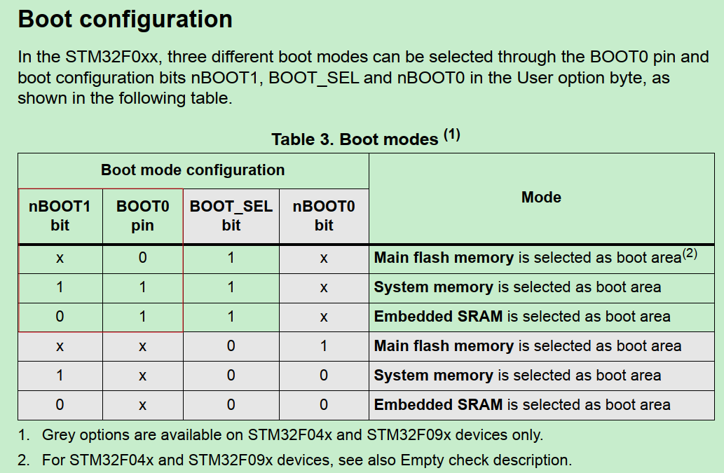
启动位置 STM32能从Flash/SRAM或System memory(远程)启动。启动位置直接决定链接脚本的加载和运行的基地址配置。
如何确认:
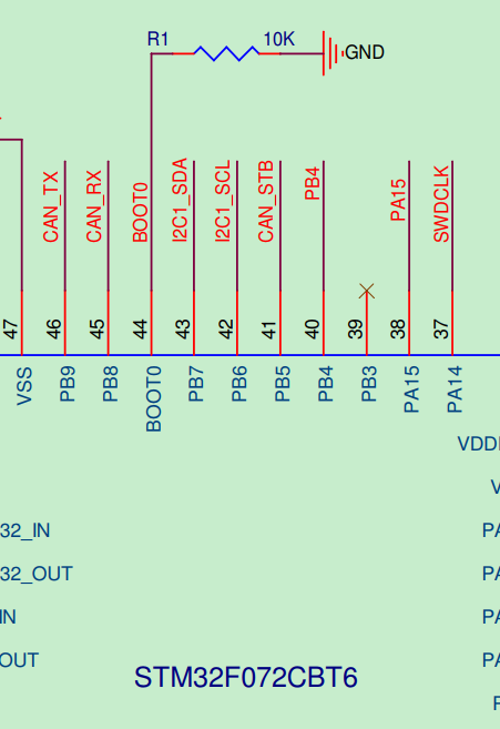
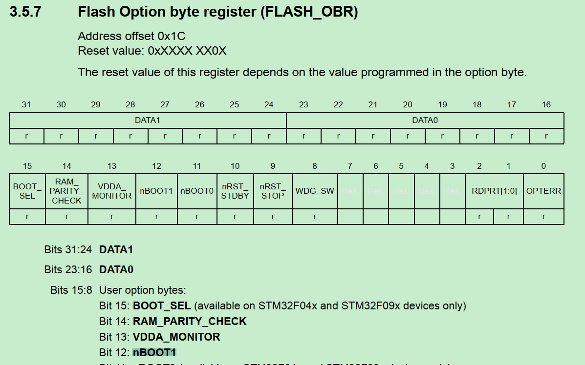
查固件包Reference Manual:对于F0系列,由BOOT0 pin和nBOOT1 register bit决定启动位置。
查开发板BOOT0 pin:下拉接地,因此开发板是Boot from Flash。
顺便查一下nBOOT1 register:
startup.s 根据链接脚本指定的asm找到启动文件startup_stm32f072xb.s
1
2
3
# ASM sources ASM_SOURCES = \ startup_stm32f072xb.s
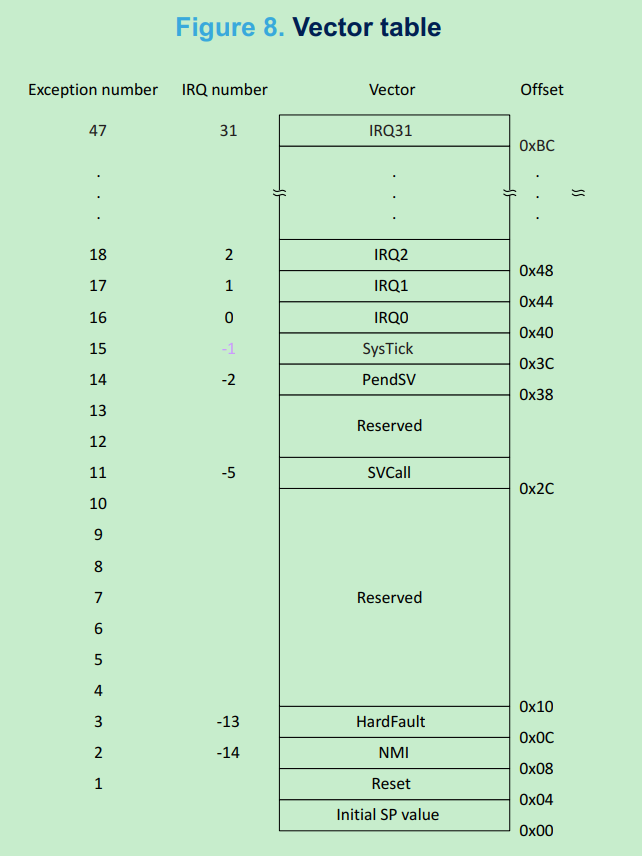
根据链接脚本的RESET符号,找到CPU复位时执行指令的入口:
1
2
3
4
5
6
7
8
9
10
11
12
13
14
15
16
17
18
19
20
21
22
23
24
25
26
27
28
29
30
31
32
33
34
35
36
37
38
39
40
41
42
43
44
45
46
47
48
49
50
51
52
53
54
55
56
57
58
59
; Vector Table Mapped to Address 0 at Reset AREA RESET, DATA, READONLY EXPORT __Vectors EXPORT __Vectors_End EXPORT __Vectors_Size __Vectors DCD __initial_sp ; Top of Stack DCD Reset_Handler ; Reset Handler DCD NMI_Handler ; NMI Handler DCD HardFault_Handler ; Hard Fault Handler DCD 0 ; Reserved DCD 0 ; Reserved DCD 0 ; Reserved DCD 0 ; Reserved DCD 0 ; Reserved DCD 0 ; Reserved DCD 0 ; Reserved DCD SVC_Handler ; SVCall Handler DCD 0 ; Reserved DCD 0 ; Reserved DCD PendSV_Handler ; PendSV Handler DCD SysTick_Handler ; SysTick Handler ; External Interrupts DCD WWDG_IRQHandler ; Window Watchdog DCD 0 ; Reserved DCD RTC_IRQHandler ; RTC through EXTI Line DCD FLASH_IRQHandler ; FLASH DCD RCC_IRQHandler ; RCC DCD EXTI0_1_IRQHandler ; EXTI Line 0 and 1 DCD EXTI2_3_IRQHandler ; EXTI Line 2 and 3 DCD EXTI4_15_IRQHandler ; EXTI Line 4 to 15 DCD 0 ; Reserved DCD DMA1_Channel1_IRQHandler ; DMA1 Channel 1 DCD DMA1_Channel2_3_IRQHandler ; DMA1 Channel 2 and Channel 3 DCD DMA1_Channel4_5_IRQHandler ; DMA1 Channel 4 and Channel 5 DCD ADC1_IRQHandler ; ADC1 DCD TIM1_BRK_UP_TRG_COM_IRQHandler ; TIM1 Break, Update, Trigger and Commutation DCD TIM1_CC_IRQHandler ; TIM1 Capture Compare DCD 0 ; Reserved DCD TIM3_IRQHandler ; TIM3 DCD 0 ; Reserved DCD 0 ; Reserved DCD TIM14_IRQHandler ; TIM14 DCD 0 ; Reserved DCD TIM16_IRQHandler ; TIM16 DCD TIM17_IRQHandler ; TIM17 DCD I2C1_IRQHandler ; I2C1 DCD 0 ; Reserved DCD SPI1_IRQHandler ; SPI1 DCD 0 ; Reserved DCD USART1_IRQHandler ; USART1 DCD USART2_IRQHandler ; USART2 DCD 0 ; Reserved DCD 0 ; Reserved DCD USB_IRQHandler ; USB __Vectors_End
这里面的AREA/DCD等伪汇编符号含义,参考[指令集与伪汇编](# 指令集与伪汇编)
以上代码声明了中断向量表,定义CPU中断、异常发生时的入口地址。
STM32 中断向量表的定义参考固件包Program Manual:
MCU启动或者reset时:
PC指针从0x0: __initial_sp取指令,此处没任何内容 此处不是个指令,而是栈顶指针的值,由编译器根据代码量+StackSize自动生成;《STM32–Firmware Architecture part2》详细分析如何生成。
然后PC + 4,从0x4取指令,即执行Reset_Handler:
1
2
3
4
5
6
7
8
9
10
; Reset handler routine Reset_Handler PROC EXPORT Reset_Handler [WEAK] IMPORT __main IMPORT SystemInit LDR R0, =SystemInit BLX R0 LDR R0, =__main BX R0 ENDP
这里先后执行SystemInit和__main
SystemInit的作用如下,o2link代码没有用此函数(空)
This function is called at startup just after reset and before branch to main program. User can setups the default system clock (System clock source, PLL Multiplier and Divider factors, AHB/APBx prescalers and Flash settings
__main符号即C的main函数 int main(void ),从此进入C代码执行。
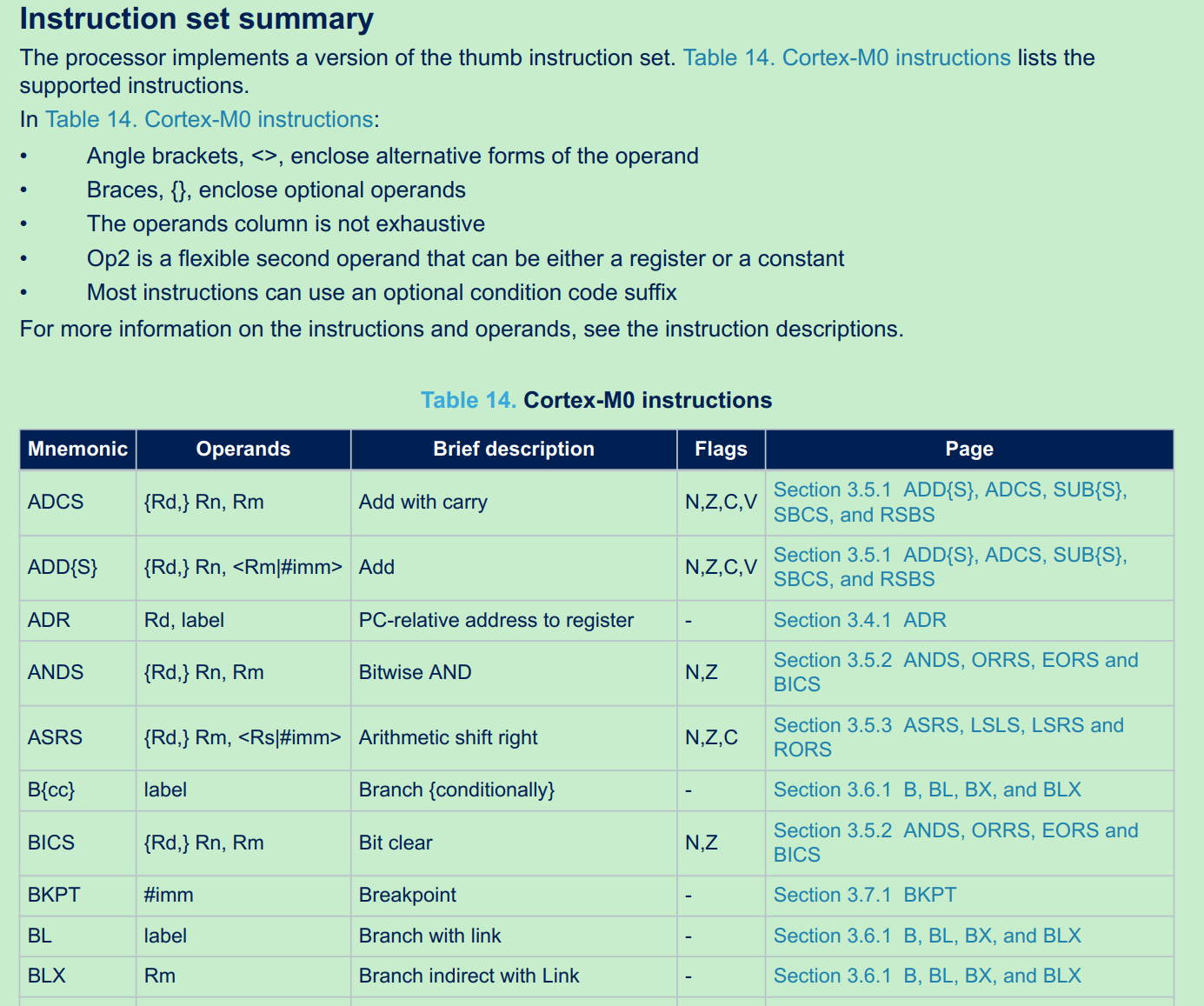
指令集与伪汇编 指令集:MCU硬件决定的指令,例如STM32是Cortex M0指令集。 详见固件包Program Manual。
伪汇编指令:是编译器扩展的汇编语法,取决于编译器类型。根据汇编器找user guide,例如 armasm:
https://documentation-service.arm.com/static/63eb50c09567172d4e2aa777
Cortex M0指令集:
armasm的一些伪汇编指令:
AREA:声明一块区域的属性,例如:AREA A64ex, CODE, READONLY; Name this block of code A64ex
EXPORT:使符号对其他文件可见。Labels are local to the source file unless you make them global using the EXPORT directive
DCD: Declares one or more words of store. 声明一块区域,如果区域是函数符号表示声明该函数所占用的区域。
STM32–main初始化流程 HAL_Init 1 2 /* Reset of all peripherals, Initializes the Flash interface and the Systick. */ HAL_Init();
1 2 3 4 /* Use systick as time base source and configure 1ms tick (default clock after Reset is HSI) */ HAL_InitTick(TICK_INT_PRIORITY); --> HAL_SYSTICK_Config: Configure the SysTick to have interrupt in 1ms time basis --> HAL_NVIC_SetPriority: Configure the SysTick IRQ priority
关于HAL_SYSTICK_Config的底层实现(参考HAL user manual.chm:
1 2 3 4 5 6 7 8 00043 (+) The HAL_SYSTICK_Config()function calls the SysTick_Config() function which 00044 is a CMSIS function that: 00045 (++) Configures the SysTick Reload register with value passed as function parameter. 00046 (++) Configures the SysTick IRQ priority to the lowest value (0x03). 00047 (++) Resets the SysTick Counter register. 00048 (++) Configures the SysTick Counter clock source to be Core Clock Source (HCLK). 00049 (++) Enables the SysTick Interrupt. 00050 (++) Starts the SysTick Counter.
关于systick的NVIC中断优先级:
* @note In the default implementation, SysTick timer is the source of time base.
* It is used to generate interrupts at regular time intervals.
* Care must be taken if HAL_Delay() is called from a peripheral ISR process,
* The SysTick interrupt must have higher priority (numerically lower)
* than the peripheral interrupt. Otherwise the caller ISR process will be blocked.
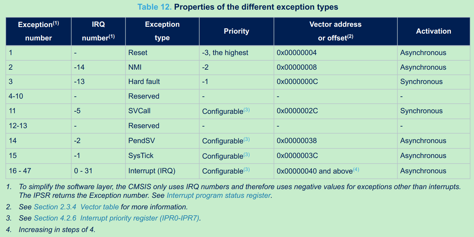
STM32 所有的中断和异常的优先级总表,参考Reference Manual:
SystemClock_Config
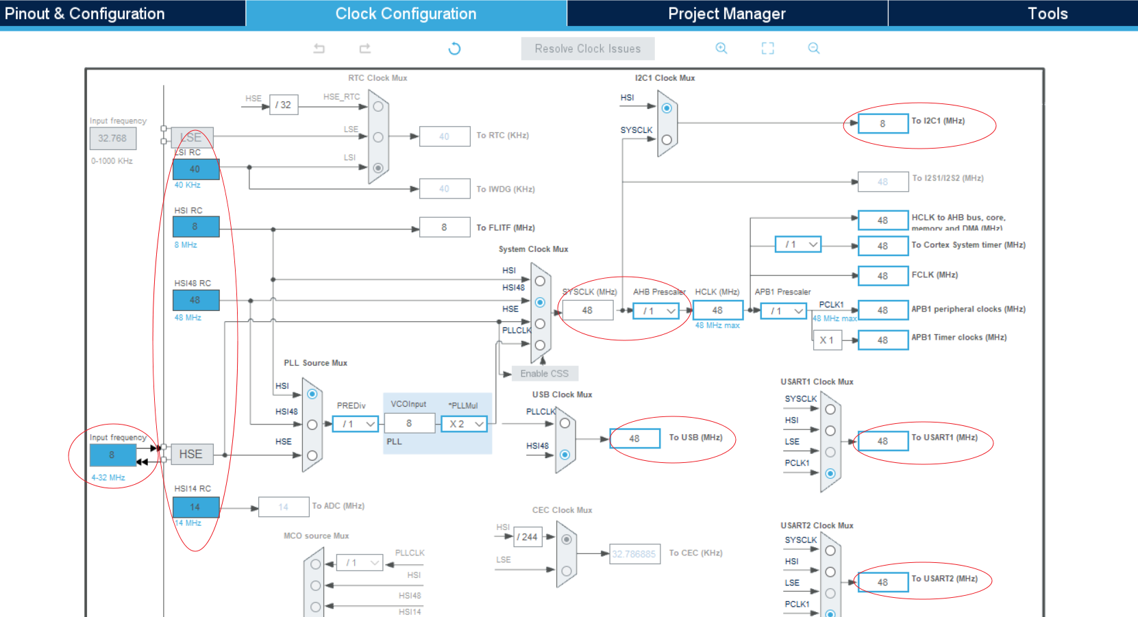
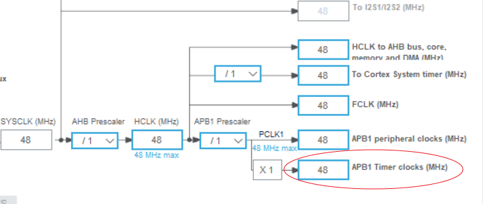
整个时钟树配置参数可以在CubeMX初始化项目时配置,系统时钟SYSCLK有外部HSE(8M OSC)和内部HSI(内部RC)多个源,由下图当前配置生效的是HSI 48M RC作为源。
不同外设模式对时钟树的要求:
I2c input frequency should up to 48M to support 1M i2c clock.
UART input frequency should be changed to HIS 8M to support lower than 1K baud rate and changed to 48M to support 1M baud rate.
USB modules need 48M input frequency
系统时钟配置过程:
1 2 /* Configure the system clock */ SystemClock_Config();
主要分两步操作:
1 2 Initializes the RCC Oscillators Initializes the CPU, AHB and APB buses clocks
具体配置过程,以HAL_RCC_OscConfig的HSI Configuration为例:
1 2 3 4 5 6 7 8 9 10 11 12 13 14 15 16 17 18 19 20 21 22 23 24 25 26 27 28 29 30 31 32 33 34 35 36 37 38 39 40 41 42 43 44 45 46 47 48 49 50 51 52 53 54 55 56 57 58 59 60 61 62 63 64 65 66 67 HAL_RCC_OscConfig: /*----------------------------- HSI Configuration --------------------------*/ if(((RCC_OscInitStruct->OscillatorType) & RCC_OSCILLATORTYPE_HSI) == RCC_OSCILLATORTYPE_HSI) { /* Check the parameters */ assert_param(IS_RCC_HSI(RCC_OscInitStruct->HSIState)); assert_param(IS_RCC_CALIBRATION_VALUE(RCC_OscInitStruct->HSICalibrationValue)); /* Check if HSI is used as system clock or as PLL source when PLL is selected as system clock */ if((__HAL_RCC_GET_SYSCLK_SOURCE() == RCC_SYSCLKSOURCE_STATUS_HSI) || ((__HAL_RCC_GET_SYSCLK_SOURCE() == RCC_SYSCLKSOURCE_STATUS_PLLCLK) && (__HAL_RCC_GET_PLL_OSCSOURCE() == RCC_PLLSOURCE_HSI))) { /* When HSI is used as system clock it will not disabled */ if((__HAL_RCC_GET_FLAG(RCC_FLAG_HSIRDY) != RESET) && (RCC_OscInitStruct->HSIState != RCC_HSI_ON)) { return HAL_ERROR; } /* Otherwise, just the calibration is allowed */ else { /* Adjusts the Internal High Speed oscillator (HSI) calibration value.*/ __HAL_RCC_HSI_CALIBRATIONVALUE_ADJUST(RCC_OscInitStruct->HSICalibrationValue); } } else { /* Check the HSI State */ if(RCC_OscInitStruct->HSIState != RCC_HSI_OFF) { /* Enable the Internal High Speed oscillator (HSI). */ __HAL_RCC_HSI_ENABLE(); /* Get Start Tick */ tickstart = HAL_GetTick(); /* Wait till HSI is ready */ while(__HAL_RCC_GET_FLAG(RCC_FLAG_HSIRDY) == RESET) { if((HAL_GetTick() - tickstart ) > HSI_TIMEOUT_VALUE) { return HAL_TIMEOUT; } } /* Adjusts the Internal High Speed oscillator (HSI) calibration value.*/ __HAL_RCC_HSI_CALIBRATIONVALUE_ADJUST(RCC_OscInitStruct->HSICalibrationValue); } else { /* Disable the Internal High Speed oscillator (HSI). */ __HAL_RCC_HSI_DISABLE(); /* Get Start Tick */ tickstart = HAL_GetTick(); /* Wait till HSI is disabled */ while(__HAL_RCC_GET_FLAG(RCC_FLAG_HSIRDY) != RESET) { if((HAL_GetTick() - tickstart ) > HSI_TIMEOUT_VALUE) { return HAL_TIMEOUT; } } } } }
这里判断HSI时钟源Ready的代码逻辑:
这里有个问题:系统时钟源还没配置完,为什么可以用HAL_GetTick去判断Ready超时,systick从哪来?
原因:CPU Reset后默认使用HSI时钟,前面的HAL_Init利用HSI初始化了1ms systick功能,因此systick可用;SystemClock_Config只是再次配置时钟,并不是说此时没有时钟。
判断时钟源ready register相关的代码:
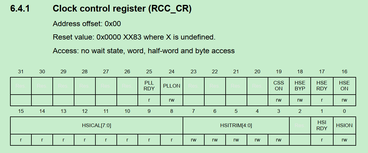
1 2 3 4 5 6 7 8 9 10 11 12 13 14 15 16 while(__HAL_RCC_GET_FLAG(RCC_FLAG_HSERDY) == RESET): typedef enum { RESET = 0U, SET = !RESET } FlagStatus, ITStatus; #define RCC_FLAG_HSERDY ((uint8_t)((CR_REG_INDEX << 5U) | RCC_CR_HSERDY_BitNumber)) #define CR_REG_INDEX ((uint8_t)1U) #define RCC_CR_HSERDY_BitNumber 17 #define __HAL_RCC_GET_FLAG(__FLAG__) (((((__FLAG__) >> 5U) == CR_REG_INDEX)? RCC->CR : \ (((__FLAG__) >> 5U) == CR2_REG_INDEX)? RCC->CR2 : \ (((__FLAG__) >> 5U) == BDCR_REG_INDEX) ? RCC->BDCR : \ RCC->CSR) & (1U << ((__FLAG__) & RCC_FLAG_MASK)))
RCC->CR的定义为例:bit17为HSE RDY bit.
MX_GPIO_Init GPIO初始化入口:
1 2 /* Initialize all configured peripherals */ MX_GPIO_Init();
GPIO重点描述几个话题:
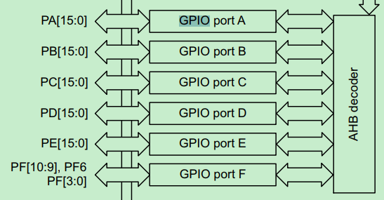
GPIO分组与复用
GPIO有A~F多组,各组的pin独立;
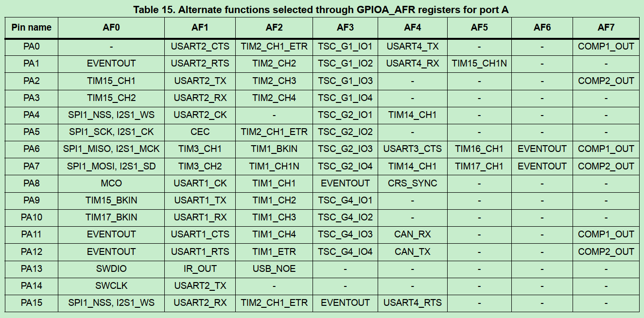
每组GPIO pin都有复用不同的功能;
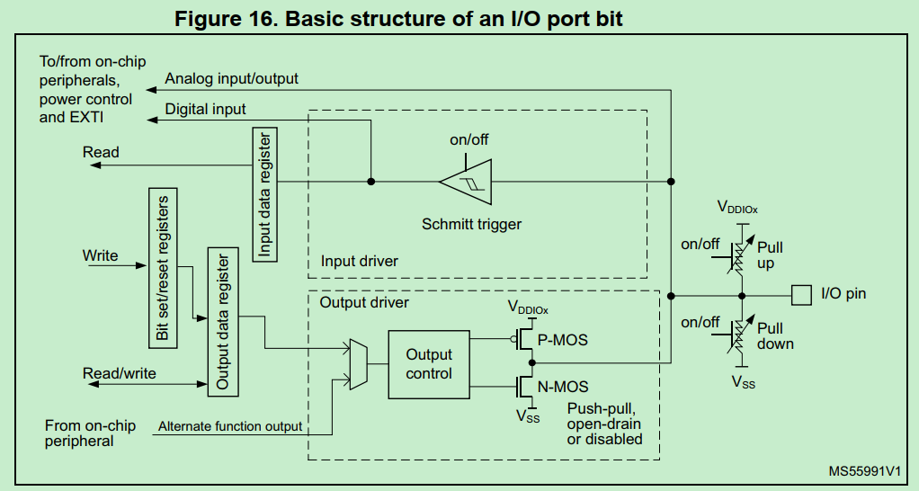
GPIO的模式
参考Datasheet:Each of the GPIO pins can be configured by software as output (push-pull or open-drain), as input (with or without pull-up or pull-down) or as peripheral alternate function.
输出模式的开漏和推挽模式的主要特性:
(1)开漏输出的高电平不是MCU驱动的,MCU仅作为控制源;输出高电平是借助外部上拉电平;可以自定义输出电平,例如3.3V/5V只需要调节上拉电平,不需受到MCU驱动能力限制。
(2)推挽输出的高电平是MCU驱动,即MCU通过内部P/N MOS结构真正输出电压(一般3.3V),MCU驱动能力有限。
GPIO代码示例(输出模式):
1 2 3 4 5 6 7 8 9 10 11 12 13 14 15 16 17 //初始化配置模式:输出,推挽 //恢复默认值(GPIO_PIN_RESET,0) /*Configure GPIO pin Output Level */ HAL_GPIO_WritePin(GPIOA, GPIO_PIN_0 | GPIO_PIN_1 | GPIO_PIN_4 | GPIO_PIN_8 | GPIO_PIN_15, GPIO_PIN_RESET); //配置模式 /*Configure GPIO pin : PA */ GPIO_InitStruct.Pin = GPIO_PIN_0 | GPIO_PIN_1 | GPIO_PIN_4 | GPIO_PIN_8 | GPIO_PIN_15; GPIO_InitStruct.Mode = GPIO_MODE_OUTPUT_PP; GPIO_InitStruct.Pull = GPIO_NOPULL; GPIO_InitStruct.Speed = GPIO_SPEED_FREQ_LOW; HAL_GPIO_Init(GPIOA, &GPIO_InitStruct); //使用:翻转PA15 HAL_GPIO_TogglePin(GPIOA, GPIO_PIN_15); //使用:设置高 HAL_GPIO_WritePin(GPIOA, GPIO_PIN_4, GPIO_PIN_SET);
GPIO中断模式:
1 2 3 4 5 6 7 8 9 10 11 12 13 14 15 16 17 18 19 20 //设置中断模式和优先级 /*Configure GPIO pin : PB */ GPIO_InitStruct.Pin = GPIO_PIN_4; GPIO_InitStruct.Mode = GPIO_MODE_IT_RISING_FALLING; //中断模式 GPIO_InitStruct.Pull = GPIO_NOPULL; HAL_GPIO_Init(GPIOB, &GPIO_InitStruct); //GPIO_MODE_IT_RISING_FALLING实际是设置EXTI中断 #define GPIO_MODE_IT_RISING_FALLING (MODE_INPUT | EXTI_IT | TRIGGER_RISING | TRIGGER_FALLING) /* EXTI interrupt init*/ HAL_NVIC_SetPriority(EXTI4_15_IRQn, 0, 0); HAL_NVIC_EnableIRQ(EXTI4_15_IRQn); //中断回调 //GPIO4实际是PB4,因为仅PB4设置为INT模式 void EXTI4_15_IRQHandler(void) { HAL_GPIO_EXTI_IRQHandler(GPIO_PIN_4); }
MX_DMA_Init DMA的常规操作 参考UM1850:
How to use this driver
Enable and configure the peripheral to be connected to the DMA Channel (except for internal SRAM /FLASH memories: no initialization is necessary). Please refer to the Reference manual for connectionbetween peripherals and DMA requests.
For a given Channel, program the required configuration through the following parameters: Channel request,Transfer Direction, Source and Destination data formats, Circular or Normal mode, Channel Priority level,Source and Destination Increment mode using HAL_DMA_Init() function.
Use HAL_DMA_GetState() function to return the DMA state and HAL_DMA_GetError() in case of errordetection.4. Use HAL_DMA_Abort() function to abort the current transfer
轮询和中断两种模式:
Polling mode IO operation
• Use HAL_DMA_Start() to start DMA transfer after the configuration of Source address and destinationaddress and the Length of data to be transferred
• Use HAL_DMA_PollForTransfer() to poll for the end of current transfer, in this case a fixed Timeout can beconfigured by User depending from his application
Interrupt mode IO operation
• Configure the DMA interrupt priority using HAL_NVIC_SetPriority()
• Enable the DMA IRQ handler using HAL_NVIC_EnableIRQ()
• Use HAL_DMA_Start_IT() to start DMA transfer after the configuration of Source address and destinationaddress and the Length of data to be transferred. In this case the DMA interrupt is configured
• Use HAL_DMA_IRQHandler() called under DMA_IRQHandler() Interrupt subroutine
• At the end of data transfer HAL_DMA_IRQHandler() function is executed and user can add his own functionby customization of function pointer XferCpltCallback and XferErrorCallback (i.e. a member of DMA handlestructure).
DMA_Init和IRQ handler DMA用于UART RX传输中断。
1 2 3 4 5 6 7 8 9 10 11 12 13 14 15 16 17 18 19 20 21 22 23 24 25 26 27 28 29 30 31 32 33 34 35 36 37 38 39 40 41 42 43 44 45 46 47 48 49 50 51 52 53 void MX_DMA_Init(void) { /* DMA controller clock enable */ __HAL_RCC_DMA1_CLK_ENABLE(); /* DMA interrupt init */ /* DMA1_Channel4_5_6_7_IRQn interrupt configuration */ HAL_NVIC_SetPriority(DMA1_Channel4_5_6_7_IRQn, 0, 0); HAL_NVIC_EnableIRQ(DMA1_Channel4_5_6_7_IRQn); } void DMA1_Channel4_5_6_7_IRQHandler(void) { HAL_DMA_IRQHandler(&hdma_usart2_rx); } Drivers\CMSIS\Device\ST\STM32F0xx\Include\stm32f072xb.h: DMA1_Channel4_5_6_7_IRQn = 11, /*!< DMA1 Channel 4 to Channel 7 Interrupt Drivers\CMSIS\Device\ST\STM32F0xx\Source\Templates\arm\startup_stm32f072xb.s: IRQ 11的handler即DMA1_Channel4_5_6_7_IRQHandler ; External Interrupts DCD WWDG_IRQHandler ; Window Watchdog DCD PVD_VDDIO2_IRQHandler ; PVD through EXTI Line detect DCD RTC_IRQHandler ; RTC through EXTI Line DCD FLASH_IRQHandler ; FLASH DCD RCC_CRS_IRQHandler ; RCC and CRS DCD EXTI0_1_IRQHandler ; EXTI Line 0 and 1 DCD EXTI2_3_IRQHandler ; EXTI Line 2 and 3 DCD EXTI4_15_IRQHandler ; EXTI Line 4 to 15 DCD TSC_IRQHandler ; TS DCD DMA1_Channel1_IRQHandler ; DMA1 Channel 1 DCD DMA1_Channel2_3_IRQHandler ; DMA1 Channel 2 and Channel 3 DCD DMA1_Channel4_5_6_7_IRQHandler ; DMA1 Channel 4, Channel 5, Channel 6 and Channel 7 UART RX 使用DMA channel 5 处理接收数据中断 HAL_UART_MspInit(): /* USART2 DMA Init */ /* USART2_RX Init */ hdma_usart2_rx.Instance = DMA1_Channel5; hdma_usart2_rx.Init.Direction = DMA_PERIPH_TO_MEMORY; hdma_usart2_rx.Init.PeriphInc = DMA_PINC_DISABLE; hdma_usart2_rx.Init.MemInc = DMA_MINC_ENABLE; hdma_usart2_rx.Init.PeriphDataAlignment = DMA_PDATAALIGN_BYTE; hdma_usart2_rx.Init.MemDataAlignment = DMA_MDATAALIGN_BYTE; hdma_usart2_rx.Init.Mode = DMA_CIRCULAR; hdma_usart2_rx.Init.Priority = DMA_PRIORITY_VERY_HIGH; if (HAL_DMA_Init(&hdma_usart2_rx) != HAL_OK) { Error_Handler(); }
HAL_DMA_IRQHandler的具体操作:
处理DMA传输完成中断:分为half transfer complete和Transfer Complete两种
1 2 3 4 5 6 7 8 9 10 11 12 13 14 15 /* Transfer Complete Interrupt management ***********************************/ else if ((RESET != (flag_it & (DMA_FLAG_TC1 << hdma->ChannelIndex))) && (RESET != (source_it & DMA_IT_TC))) { if((hdma->Instance->CCR & DMA_CCR_CIRC) == 0U) { /* Disable the transfer complete & transfer error interrupts */ /* if the DMA mode is not CIRCULAR */ hdma->Instance->CCR &= ~(DMA_IT_TC | DMA_IT_TE); /* Change the DMA state */ hdma->State = HAL_DMA_STATE_READY; } /* Clear the transfer complete flag */ hdma->DmaBaseAddress->IFCR = DMA_FLAG_TC1 << hdma->ChannelIndex;
DMA传输完成的回调函数:
1 2 3 4 5 if(hdma->XferCpltCallback != NULL) { /* Transfer complete callback */ hdma->XferCpltCallback(hdma); }
o2link的UART2处理1KB DMA buffer的自定义逻辑,就是在此中断回调中实现。
1 2 3 UART_Start_Receive_DMA(): /* Set the UART DMA transfer complete callback */ huart->hdmarx->XferCpltCallback = UART_DMAReceiveCplt;
DMA传输错误中断的判断和回调函数:
1 2 3 4 5 6 7 8 9 10 11 12 13 14 15 16 17 18 19 20 21 22 23 24 25 26 /* Transfer Error Interrupt management ***************************************/ else if (( RESET != (flag_it & (DMA_FLAG_TE1 << hdma->ChannelIndex))) && (RESET != (source_it & DMA_IT_TE))) { /* When a DMA transfer error occurs */ /* A hardware clear of its EN bits is performed */ /* Then, disable all DMA interrupts */ hdma->Instance->CCR &= ~(DMA_IT_TC | DMA_IT_HT | DMA_IT_TE); /* Clear all flags */ hdma->DmaBaseAddress->IFCR = DMA_FLAG_GL1 << hdma->ChannelIndex; /* Update error code */ hdma->ErrorCode = HAL_DMA_ERROR_TE; /* Change the DMA state */ hdma->State = HAL_DMA_STATE_READY; /* Process Unlocked */ __HAL_UNLOCK(hdma); if(hdma->XferErrorCallback != NULL) { /* Transfer error callback */ hdma->XferErrorCallback(hdma); } }
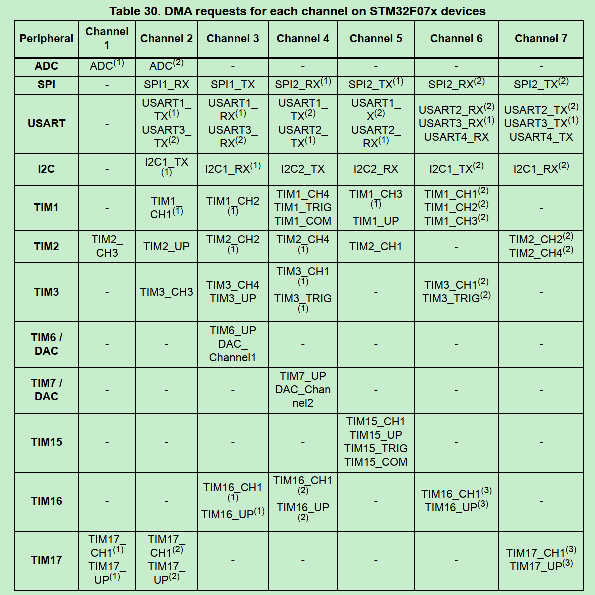
DMA channel和外设的对应关系 参考(RM0091):
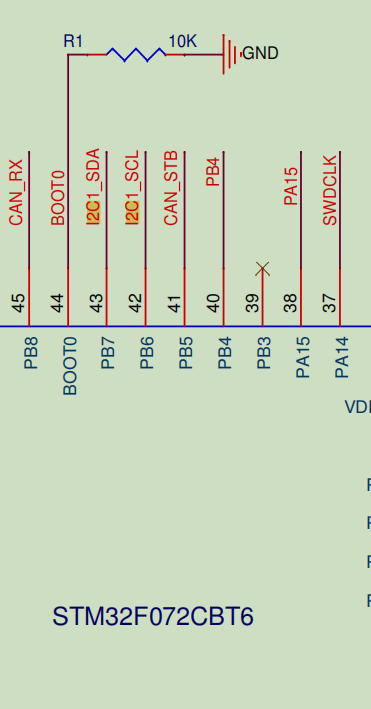
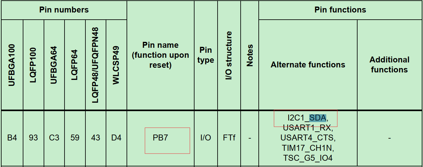
MX_I2C1_Init 首先明确一个问题:是硬件实现的I2C还是软件GPIO模拟的I2C?
怎么确认:看电路图+Datasheet+底层数据传输代码
硬件I2C:此GPIO应该支持I2C功能,Datasheet确认,软件查看是否配成了I2C功能,数据传输是否配置I2C register
软件I2C:此GPIO是普通的GPIO功能,用软件控制high、low和delay控制I2C数据传输,底层操作不是用I2C register实现。
根据以下,本环境是硬件I2C功能。
下面看初始化代码。
I2C初始化包括两步:
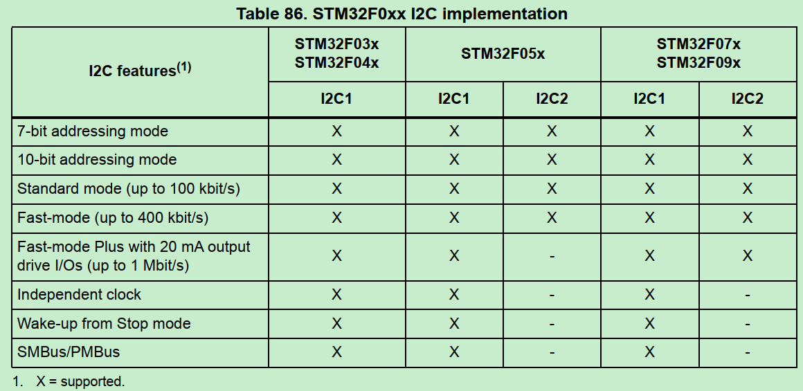
设置I2C通信参数
速度:standard (up to 100 kHz), Fast-mode (up to 400 kHz) or Fast-mode Plus (up to 1 MHz)
寻址:7-bit/10 bit addressing mode,决定i2c slave设备寻址空间
其他能力见RM0091:
代码配置的速度和寻址:
1 2 hi2c1.Init.Timing = SETTING_CLK_100K; hi2c1.Init.AddressingMode = I2C_ADDRESSINGMODE_7BIT;
配置GPIO pin为I2C模式
1 2 3 4 5 6 7 8 9 10 11 12 13 14 15 16 HAL_I2C_Init --> HAL_I2C_MspInit: /**I2C1 GPIO Configuration PB6 ------> I2C1_SCL PB7 ------> I2C1_SDA */ GPIO_InitStruct.Pin = GPIO_PIN_6 | GPIO_PIN_7; GPIO_InitStruct.Mode = GPIO_MODE_AF_OD; GPIO_InitStruct.Pull = GPIO_NOPULL; GPIO_InitStruct.Speed = GPIO_SPEED_FREQ_HIGH; GPIO_InitStruct.Alternate = GPIO_AF1_I2C1; HAL_GPIO_Init(GPIOB, &GPIO_InitStruct);
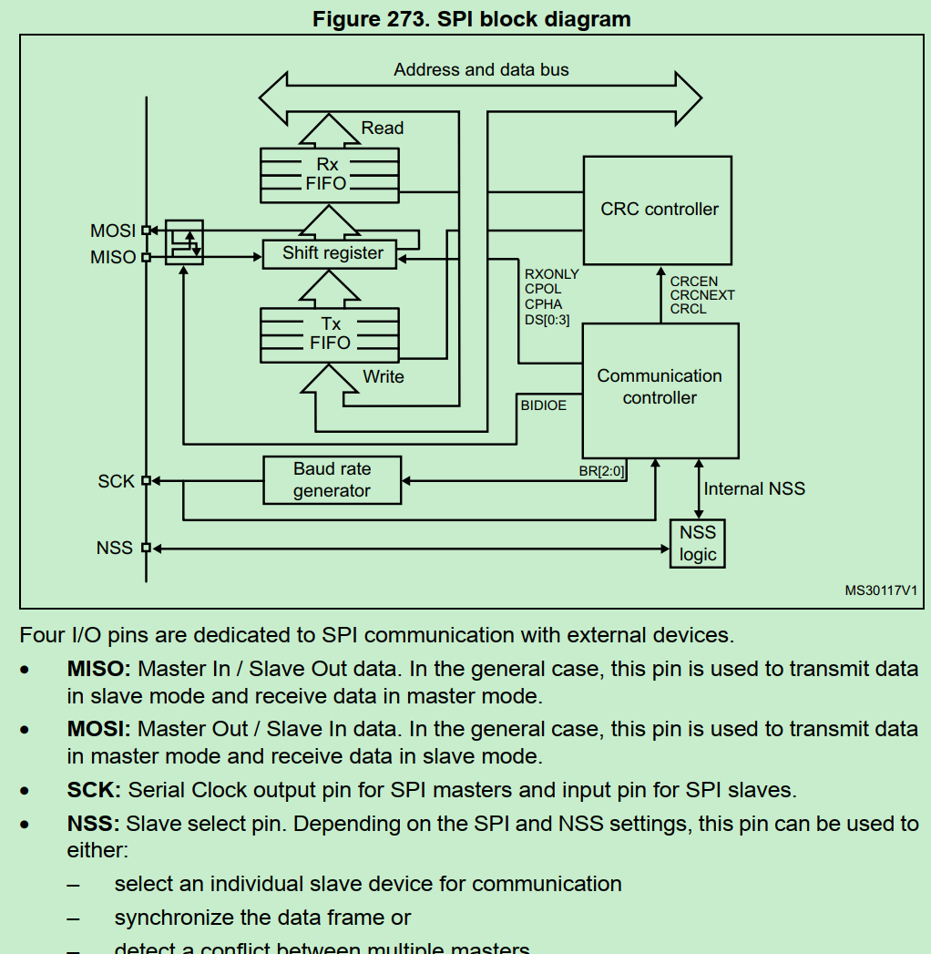
MX_SPI1_Init 和I2C初始化结构基本类似
设置SPI通信参数
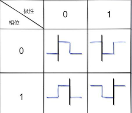
1 2 3 4 5 hspi1.Init.Mode = SPI_MODE_MASTER; hspi1.Init.Direction = SPI_DIRECTION_2LINES; //双向 hspi1.Init.DataSize = SPI_DATASIZE_8BIT; //数据是8bit模式 hspi1.Init.CLKPolarity = SPI_POLARITY_HIGH; // hspi1.Init.CLKPhase = SPI_PHASE_2EDGE;
关于SPI配置,主要关注数据模式是8bit还是16bit, 以及数据采样和传输的时间点(极性和相位)。
参考SPI的四种传输模式及工作机制分析
黑线为数据采样点,与之相反为数据发送点
设置GPIO为SPI模式
1 2 3 4 5 6 7 8 9 10 11 /**SPI1 GPIO Configuration PA5 ------> SPI1_SCK PA6 ------> SPI1_MISO PA7 ------> SPI1_MOSI */ GPIO_InitStruct.Pin = GPIO_PIN_5|GPIO_PIN_6|GPIO_PIN_7; GPIO_InitStruct.Mode = GPIO_MODE_AF_PP; GPIO_InitStruct.Pull = GPIO_NOPULL; GPIO_InitStruct.Speed = GPIO_SPEED_FREQ_HIGH; GPIO_InitStruct.Alternate = GPIO_AF0_SPI1; HAL_GPIO_Init(GPIOA, &GPIO_InitStruct);
MX_USART1_UART_Init 对于o2link board, 使用三个UART:
(1) UART 1 PA9 PA10 is used as debug port.
(2) UART 2 PA2 PA3 is used as USB TO UART port
(3) UART 3 PB10 PB11 is used as system communication port.
本节讨论UART1
设置UART通信参数
1 2 3 4 5 6 huart1.Instance = USART1; huart1.Init.BaudRate = 115200; //波特率 huart1.Init.WordLength = UART_WORDLENGTH_8B; //8-bit long UART frame(可配7,8,9bit) huart1.Init.StopBits = UART_STOPBITS_1; huart1.Init.Parity = UART_PARITY_NONE; huart1.Init.Mode = UART_MODE_TX_RX; //双向
设置GPIO为UART模式
1 2 3 4 5 6 7 8 9 10 /**USART1 GPIO Configuration PA9 ------> USART1_TX PA10 ------> USART1_RX */ GPIO_InitStruct.Pin = GPIO_PIN_9 | GPIO_PIN_10; GPIO_InitStruct.Mode = GPIO_MODE_AF_PP; GPIO_InitStruct.Pull = GPIO_PULLUP; GPIO_InitStruct.Speed = GPIO_SPEED_FREQ_HIGH; GPIO_InitStruct.Alternate = GPIO_AF1_USART1; HAL_GPIO_Init(GPIOA, &GPIO_InitStruct);
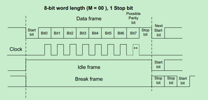
UART Idle frame和Break frame的概念
为什么UART pin默认拉高?
UART除了正常的数据传输情况,还有idle和break frame的特殊情况:
An Idle character is interpreted as an entire frame of “1”s (the number of “1”s includes the number of stop bits).
A Break character is interpreted on receiving “0”s for a frame period. At the end of the break frame, the transmitter inserts 2 stop bits.
默认上拉, 如果MCU没有drive UART RX/TX pin为低,则可以识别为idle frame;
默认上拉,UART start时MCU开始drive RX/TX, 直接拉低pin形成Start信号。
MX_USART2_UART_Init o2link的UART 2 PA2 PA3 is used as USB TO UART port.
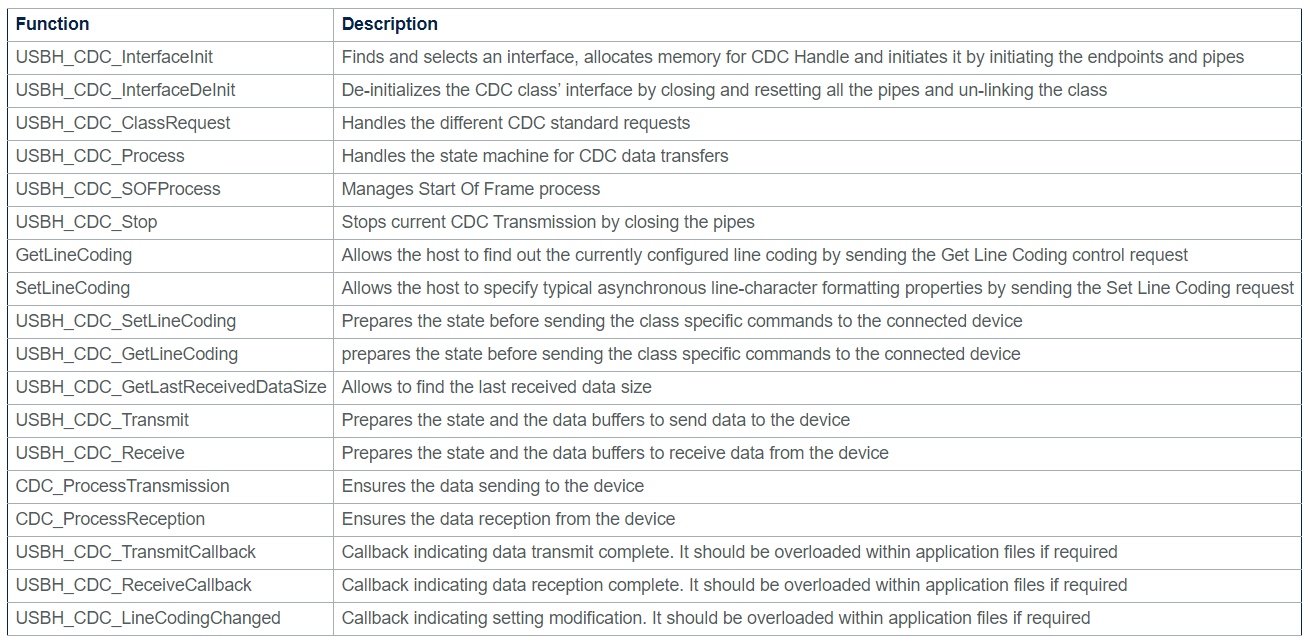
什么是USB to UART:涉及USB CDC虚拟串口的概念,参考: Communications Devices Class (CDC) ,即USB实现的虚拟串口协议;
MCU侧配置UART2参数是来自于USBD_CDC_LineCoding.
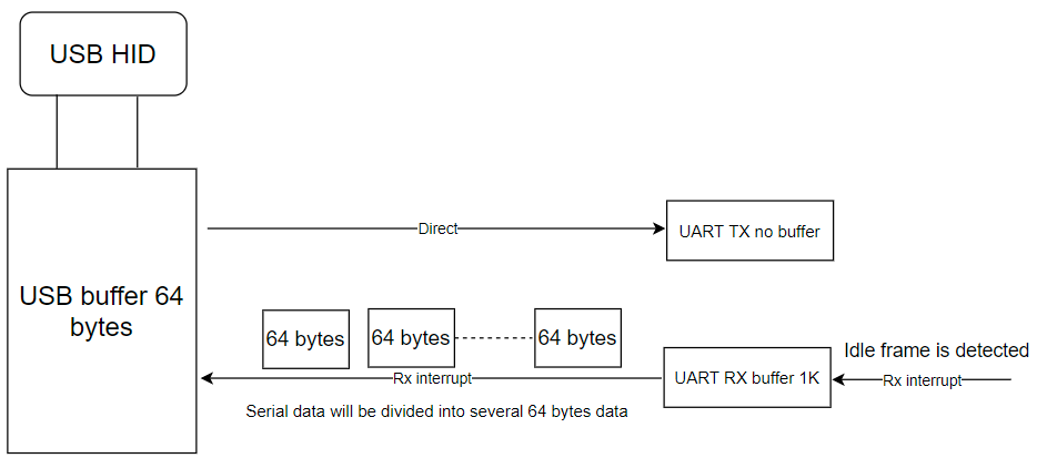
对于o2link的USB to UART2:
UART TX has no buffer, it will send data directly to the TX pin when it receives data from USB HID, the max data is 64 bytes one time. UART RX has 1K bytes buffer, it uses idle frame to receive data, when it sees this idle frame, it will generate interrupt to tell the app code, and the app code will split data into 64 bytes and transmit the data to the USB.
UART2初始化过程
根据USB CDC的配置,设置UART2参数
1 2 3 4 5 6 7 8 9 10 11 12 13 14 15 16 17 18 19 20 21 22 23 24 25 26 27 28 29 30 31 32 33 34 35 36 37 38 39 40 41 42 43 44 45 46 47 48 49 50 51 52 53 54 55 56 57 58 void MX_USART2_UART_Init(uint32_t baurate) { USBD_CDC_LineCoding.bitrate = baurate; //1000 000 USBD_CDC_LineCoding.paritytype = UART_PARITY_NONE; USBD_CDC_LineCoding.datatype = UART_WORDLENGTH_8B; USBD_CDC_LineCoding.format = UART_STOPBITS_1; UART2_Init(); } UART2_Init(): huart2.Init.BaudRate = USBD_CDC_LineCoding.bitrate; switch (USBD_CDC_LineCoding.paritytype) { case 0: huart2.Init.Parity = UART_PARITY_NONE; break; case 1: huart2.Init.Parity = UART_PARITY_ODD; break; case 2: huart2.Init.Parity = UART_PARITY_EVEN; break; default: huart3.Init.Parity = UART_PARITY_NONE; break; } switch (USBD_CDC_LineCoding.datatype) { case 0x07: huart2.Init.WordLength = UART_WORDLENGTH_8B; break; case 0x08: if (huart2.Init.Parity == UART_PARITY_NONE) { huart2.Init.WordLength = UART_WORDLENGTH_8B; } else { huart2.Init.WordLength = UART_WORDLENGTH_9B; } break; default: huart2.Init.WordLength = UART_WORDLENGTH_8B; break; } switch (USBD_CDC_LineCoding.format) { case 0: huart2.Init.StopBits = UART_STOPBITS_1; break; case 2: huart2.Init.StopBits = UART_STOPBITS_2; break; default: huart2.Init.StopBits = UART_STOPBITS_1; break; }
配置GPIO,配置UART使用DMA模式
1 2 3 4 5 6 7 8 9 10 11 12 13 14 15 16 17 18 19 20 21 22 23 24 25 26 27 28 29 30 31 /**USART2 GPIO Configuration PA2 ------> USART2_TX PA3 ------> USART2_RX */ GPIO_InitStruct.Pin = GPIO_PIN_2 | GPIO_PIN_3; GPIO_InitStruct.Mode = GPIO_MODE_AF_PP; GPIO_InitStruct.Pull = GPIO_PULLUP; GPIO_InitStruct.Speed = GPIO_SPEED_FREQ_HIGH; GPIO_InitStruct.Alternate = GPIO_AF1_USART2; HAL_GPIO_Init(GPIOA, &GPIO_InitStruct); /* USART2 DMA Init */ /* USART2_RX Init */ hdma_usart2_rx.Instance = DMA1_Channel5; hdma_usart2_rx.Init.Direction = DMA_PERIPH_TO_MEMORY; hdma_usart2_rx.Init.PeriphInc = DMA_PINC_DISABLE; hdma_usart2_rx.Init.MemInc = DMA_MINC_ENABLE; hdma_usart2_rx.Init.PeriphDataAlignment = DMA_PDATAALIGN_BYTE; hdma_usart2_rx.Init.MemDataAlignment = DMA_MDATAALIGN_BYTE; hdma_usart2_rx.Init.Mode = DMA_CIRCULAR; hdma_usart2_rx.Init.Priority = DMA_PRIORITY_VERY_HIGH; if (HAL_DMA_Init(&hdma_usart2_rx) != HAL_OK) { Error_Handler(); } __HAL_LINKDMA(uartHandle, hdmarx, hdma_usart2_rx); /* USART2 interrupt Init */ HAL_NVIC_SetPriority(USART2_IRQn, 0, 0); HAL_NVIC_EnableIRQ(USART2_IRQn);
启动DMA,随时准备处理UART RX的数据
1 2 3 4 5 6 7 8 9 10 11 12 13 14 15 16 reset_uart_buffer() --> HAL_UARTEx_ReceiveToIdle_DMA(&huart2, UART2_RxBuffer, UART_PACKAGE_MAX_SIZE); 参数如下: * @param huart UART handle. * @param pData Pointer to data buffer (uint8_t or uint16_t data elements). * @param Size Amount of data elements (uint8_t or uint16_t) to be received. 其中UART2_RxBuffer是1KB buffer, UART_PACKAGE_MAX_SIZE = 1024 HAL_UARTEx_ReceiveToIdle_DMA的内容: /* Set Reception type to reception till IDLE Event*/ huart->ReceptionType = HAL_UART_RECEPTION_TOIDLE; //Reception till completion or IDLE event. 即UART有idle frame能产生DMA中断,不一定要传输完整个buffer的1KB数据。 //启动DMA status = UART_Start_Receive_DMA(huart, pData, Size);
启动DMA传输的过程:
1 2 3 4 5 6 UART_Start_Receive_DMA(): /* Set the UART DMA transfer complete callback */ huart->hdmarx->XferCpltCallback = UART_DMAReceiveCplt; /* Enable the DMA channel */ HAL_DMA_Start_IT()
UART_DMAReceiveCplt里面自定义了完成的处理:
1 2 3 4 5 6 7 8 9 10 11 12 13 14 15 16 17 18 19 20 21 22 23 24 25 26 27 28 29 30 UART_DMAReceiveCplt() --> HAL_UARTEx_RxEventCallback(): void HAL_UARTEx_RxEventCallback(UART_HandleTypeDef *huart, uint16_t Size) { /* Prevent unused argument(s) compilation warning */ UNUSED(huart); UNUSED(Size); if (huart->Instance == USART2) { //Size是DMA已传输完的总长度(DMA硬件自动计算) //Rx_buf_pos是firmware自定义, 记录RX buffer的偏移。 //Rx_length即当前DMA complete的传输数据长度(不包括历史总长度) Rx_length = Size - Rx_buf_pos; if ((Size < Rx_buf_pos) || (Size > UART_PACKAGE_MAX_SIZE)) { Rx_buf_pos = Size; if (Rx_buf_pos >= UART_PACKAGE_MAX_SIZE) Rx_buf_pos = 0; printf("dma buffer error\r\n "); return; } //这里uart_rx_fifo和UART2_RxBuffer都是1KB buffer,uart_rx_fifo用于每次DMA的buffer,每次数据都从0开始存;UART2_RxBuffer是存储多次DMA的总数据,按偏移组合; fifo_s_puts(&uart_rx_fifo, (char *)&UART2_RxBuffer[Rx_buf_pos], Rx_length); Rx_buf_pos += Rx_length; if (Rx_buf_pos >= UART_PACKAGE_MAX_SIZE) //1024 Rx_buf_pos = 0; } }
理解以上代码,就可以理解USB to UART2的RX机制,是将下位机的大量UART data(最多1024 bytes),分多次DMA存到UART2_RxBuffer,再按64bytes/USB buffer发给上位机。
UART的DMA传输小结 UART为什么使用DMA:
常规的UART传输,不管是轮询还是中断,一般需要先指定好传输长度是多少个byte,即必须数据长度已知。
常规的UART传输如何知道传输完成:
如果是轮询就预估超时时间,如果是中断就按传输完成多少byte作为标志。
使用DMA中断的UART传输,可以支持不定长度的数据。
使用DMA的UART如何知道传输完成:
数据传输完成;或者有UART event如Idle event,RTO event…
MX_USART3_UART_Init UART 3 PB10 PB11 is used as system communication port.
和UART1配置区别仅在波特率,uart3实例没实际使用。
1 huart3.Init.BaudRate = 1000000;
1 2 3 4 5 6 7 8 9 10 /**USART3 GPIO Configuration PB10 ------> USART3_TX PB11 ------> USART3_RX */ GPIO_InitStruct.Pin = GPIO_PIN_10 | GPIO_PIN_11; GPIO_InitStruct.Mode = GPIO_MODE_AF_PP; GPIO_InitStruct.Pull = GPIO_PULLUP; GPIO_InitStruct.Speed = GPIO_SPEED_FREQ_HIGH; GPIO_InitStruct.Alternate = GPIO_AF4_USART3; HAL_GPIO_Init(GPIOB, &GPIO_InitStruct);
MX_USB_DEVICE_Init USB设备的功能实现从上到下分为几层API:
1 2 3 4 5 6 Middleware层的USB API:usbd_core (.c, .h), 例如USBD_Init --> Low level层的USB API:例如USBD_LL_Init --> HAL的USB host或peripheral API:例如HAL_PCD_Init HCD:USB host controller driver PCD:USB peripheral controller driver
参考: USB device library overview
下面具体分析USB初始化各层负责什么工作:
USBD_Init:Initializes the device stack and load the class driver. 负责USB协议范畴的设备class,设备descriptor等信息的处理。
1 2 3 4 5 6 7 8 9 10 11 12 13 14 15 /* Unlink previous class*/ if (pdev->pClass != NULL) { pdev->pClass = NULL; } /* Assign USBD Descriptors */ if (pdesc != NULL) { pdev->pDesc = pdesc; } /* Set Device initial State */ pdev->dev_state = USBD_STATE_DEFAULT; pdev->id = id;
USBD_LL_Init:Initializes the low level portion of the device driver. 负责PCD设备对象的初始化,包括设备属性,设备初始化,DMA配置。
1 2 3 4 5 6 7 8 9 10 11 12 13 14 15 16 17 18 19 20 21 22 23 24 25 26 27 28 29 30 PCD_HandleTypeDef hpcd_USB_FS; /* Link the driver to the stack. */ hpcd_USB_FS.pData = pdev; pdev->pData = &hpcd_USB_FS; //设备属性 hpcd_USB_FS.Instance = USB; hpcd_USB_FS.Init.dev_endpoints = 8; hpcd_USB_FS.Init.speed = PCD_SPEED_FULL; hpcd_USB_FS.Init.phy_itface = PCD_PHY_EMBEDDED; hpcd_USB_FS.Init.low_power_enable = DISABLE; hpcd_USB_FS.Init.lpm_enable = DISABLE; hpcd_USB_FS.Init.battery_charging_enable = DISABLE; //设备初始化 if (HAL_PCD_Init(&hpcd_USB_FS) != HAL_OK) { Error_Handler( ); } //DMA配置 HAL_PCDEx_PMAConfig((PCD_HandleTypeDef*)pdev->pData , 0x00 , PCD_SNG_BUF, 0x28); HAL_PCDEx_PMAConfig((PCD_HandleTypeDef*)pdev->pData , 0x80 , PCD_SNG_BUF, 0x80); HAL_PCDEx_PMAConfig((PCD_HandleTypeDef*)pdev->pData , CUSTOM_HID_EPIN_ADDR , PCD_SNG_BUF, 0xc0); HAL_PCDEx_PMAConfig((PCD_HandleTypeDef*)pdev->pData , CUSTOM_HID_EPOUT_ADDR , PCD_SNG_BUF, 0x100); HAL_PCDEx_PMAConfig((PCD_HandleTypeDef*)pdev->pData , CDC_IN_EP , PCD_SNG_BUF, 0x140); HAL_PCDEx_PMAConfig((PCD_HandleTypeDef*)pdev->pData , CDC_OUT_EP , PCD_SNG_BUF, 0x180); HAL_PCDEx_PMAConfig((PCD_HandleTypeDef*)pdev->pData , CDC_CMD_EP , PCD_SNG_BUF, 0x1c0);
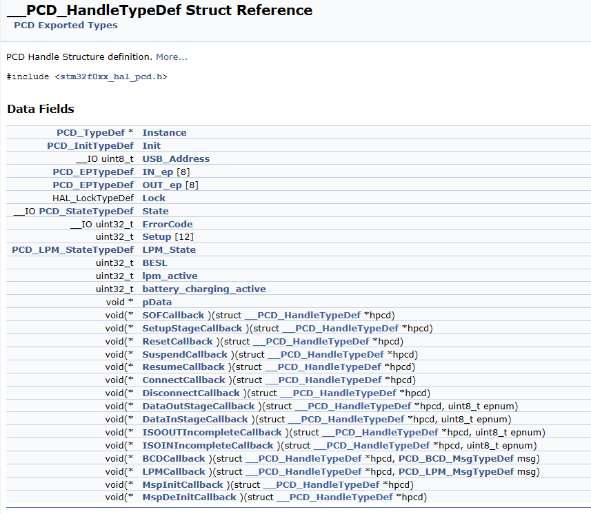
USB设备对象PCD_HandleTypeDef的定义:
初始化完成后是USBD_RegisterClass和USBD_Start,结构类似不细讲。
最终通过HAL_PCD_Start返回的USBD_OK status确认初始化OK。
MX_CAN_Init 目前o2link没使用MX_CAN_Init,代码为空
MX_TIM6_Init 关于timer有两点背景:
hardware timer和systick(Cortex System Timer)的区别:
从大概功能上看,都是计时器计数产生中断;
主要是应用上的区别:
a. systick精度一般是1ms,属于系统运行时就一直产生中断,生命周期不停的计时器;常用于应用层的ms_delay延时。
b. hardware timer精度可以达到us, ns,属于即用即停,单次运行的计时器;常用于硬件操作相关的,比如时序要求的us_delay延时。
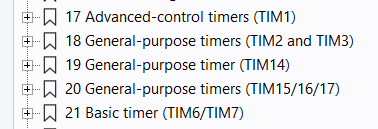
STM32的hardware timer有几类:
o2link只用到base timer 6. 以下讨论都是针对base timer 6
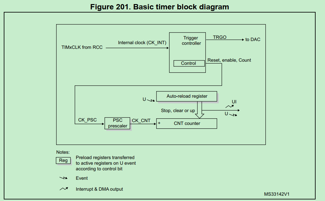
timer的计时原理图
timer的计时精度和最大时间
对timer模块时钟的分频决定精度:
1 2 #define TIME_BASE_1US 48 #define TIME_BASE_100US 4800
timer模块的时钟是48MHZ, 所以48分频为1us计时.
1 2 3 4 htim6.Init.Prescaler = Prescaler - 1; //分频后的时钟,决定每个counter计数的时间间隔 htim6.Init.CounterMode = TIM_COUNTERMODE_UP; //counter累加模式 htim6.Init.Period = 0xffff; //最大counter数:65535 htim6.Init.AutoReloadPreload = TIM_AUTORELOAD_PRELOAD_ENABLE; //counter满后自动reload计数
o2link设置timer6的Prescaler = 4800, 即100us/count,最大时间是100us*65535,约6.5s。
o2link对timer6的应用示例:
1 2 3 4 5 6 HAL_TIM_Base_Start_IT(&htim6); while (one_wire_timer_counter_100US < one_wire_parameter.sync_high_time){}; HAL_TIM_Base_Stop_IT(&htim6); 其中: #define one_wire_timer_counter_100US (htim6.Instance->CNT * 100) // 转化成微秒
使能irq和systick 全部外设配置完毕,启动系统:
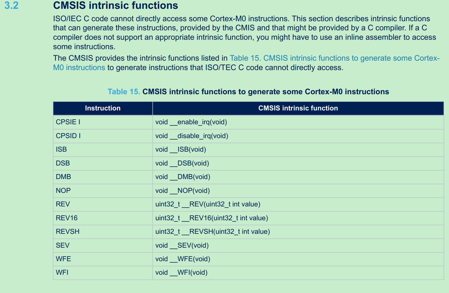
enable irq:
1 2 3 4 5 6 7 8 9 /** \brief Enable IRQ Interrupts \details Enables IRQ interrupts by clearing the I-bit in the CPSR. Can only be executed in Privileged modes. */ __STATIC_FORCEINLINE void __enable_irq(void) { __ASM volatile ("cpsie i" : : : "memory"); }
enable systick:
1 2 3 4 5 6 7 8 9 10 11 12 13 14 15 16 17 18 19 20 void systime_init() { systime_tick.tick_ms = 0; systime_tick.tick_10ms = 0; systime_tick.tick_100ms = 0; systime_tick.tick_sec = 0; systime_tick.tick_min = 0; systime_tick.tick_hour = 0; } /** * @brief: Start systick, including IRQ (TBD) * Used when system is powered on * @param: None * @return: None */ void systime_start(void) { SysTick->CTRL |= (SysTick_CTRL_ENABLE_Msk | SysTick_CTRL_TICKINT_Msk); }
STM32–while loop业务流程 以下分析基于o2link firmware
while(1)的处理主要分为几大类:
用systick更新应用时间
处理UART DMA的RX buffer的数据
处理USB下发的控制信号
systick管理时间 这个目前没什么应用,仅用于LED闪烁;真实用户场景可能用到
1 2 3 4 5 6 7 8 9 10 11 12 13 14 15 16 17 18 systime_update(): void systime_update(void) { if (systime_tick.tick_ms != HAL_GetTick()) { systime_tick.tick_ms = HAL_GetTick(); if ((systime_tick.tick_ms % TICKRATE_10MS) == (TICKRATE_10MS - 1)) systime_tick.tick_10ms++; if ((systime_tick.tick_ms % TICKRATE_100MS) == (TICKRATE_100MS - 1)) systime_tick.tick_100ms++; if ((systime_tick.tick_ms % TICKRATE_HZ) == (TICKRATE_HZ - 1)) { systime_tick.tick_sec++; systime_tick.tick_min = (systime_tick.tick_sec / MIN_UNIT); systime_tick.tick_hour = (systime_tick.tick_sec / HOUR_UNIT); } } }
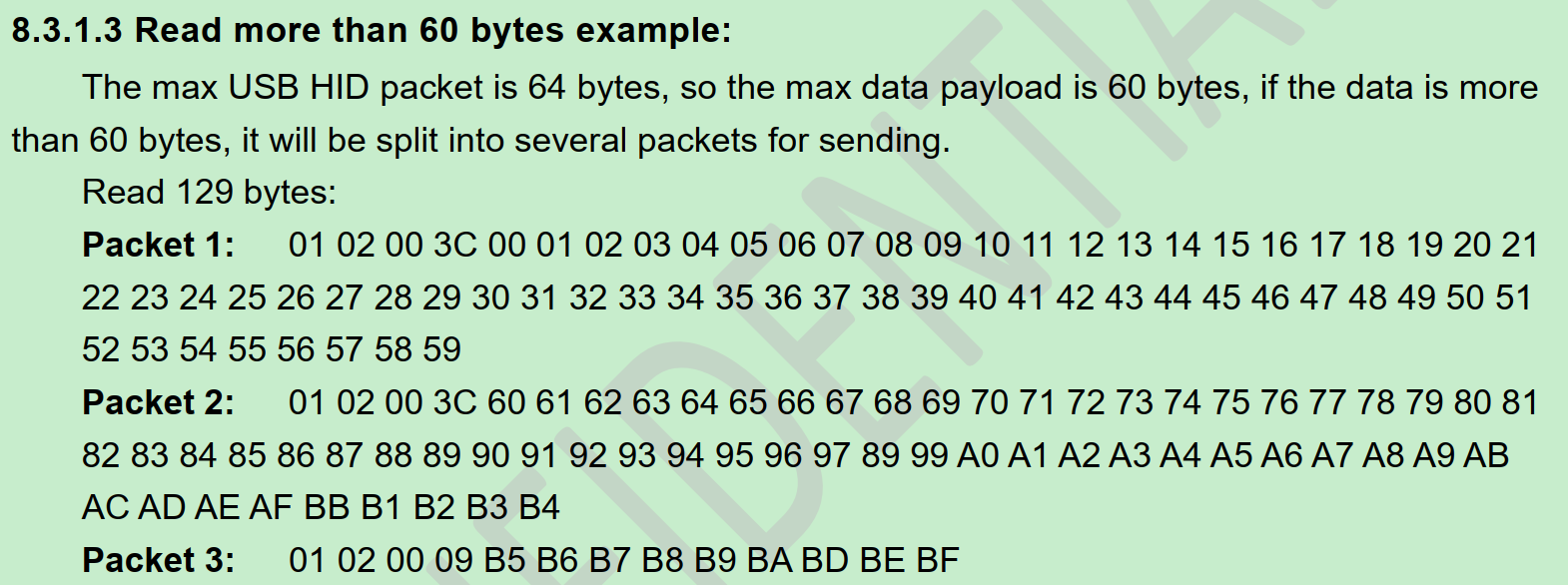
处理UART RX的DMA数据 UART从RX的DMA buffer中返回给USB接口,有USB-HID和USB-CDC两种形式:
1 2 3 4 5 6 7 8 9 10 11 12 13 14 15 16 17 18 19 20 21 22 23 24 25 26 27 28 29 30 31 32 33 34 35 36 37 38 39 40 41 uart_data_analysis(): void uart_data_analysis(void) { uint32_t len; uint8_t usb_back_buf[64] = {0}; //USB的buffer uint8_t *buffer = inter_buffer; len = fifo_s_used(&uart_rx_fifo); // 待发送数据长度 if (len > 0) { fifo_s_gets(&uart_rx_fifo, (char *)inter_buffer, len); //从FIFO取数据 if (cdc_receive_flag == 0) //no CDC,即HID模式 { while (len > 0) //fifo取到数据? { usb_back_buf[0] = 0x01; //见o2link spec, 0101 for UART usb_back_buf[1] = 0x01; //fifo取了60bytes是否还有多的?4bytes是USB加的header if (len > MAX_USB_UART_PACKET_NUM) { usb_back_buf[2] = (MAX_USB_UART_PACKET_NUM & 0xff00) >> 8; usb_back_buf[3] = (MAX_USB_UART_PACKET_NUM & 0x00ff); memcpy(&usb_back_buf[4], buffer, MAX_USB_UART_PACKET_NUM); usb_send(usb_back_buf, USB_TIMEOUT_TIME); len -= MAX_USB_UART_PACKET_NUM; buffer += MAX_USB_UART_PACKET_NUM; } else //fifo数据小于60bytes { usb_back_buf[2] = (len & 0xff00) >> 8; usb_back_buf[3] = (len & 0x00ff); memcpy(&usb_back_buf[4], buffer, len); usb_send(usb_back_buf, USB_TIMEOUT_TIME); len = 0; } } } else //USB-CDC模式 CDC_Transmit_FS(inter_buffer, len, USB_TIMEOUT_TIME); } }
USB-HID发送数据的实现:
1 2 3 4 5 6 7 8 9 10 11 12 13 uint8_t usb_send(uint8_t *send_data,uint32_t time_out) { uint32_t tickstart = 0U; tickstart = HAL_GetTick(); while(1) { if(USBD_OK == USBD_CUSTOM_HID_SendReport(&hUsbDeviceFS, send_data, USBD_CUSTOMHID_OUTREPORT_BUF_SIZE)) return USBD_OK; if((HAL_GetTick() - tickstart) > time_out) return USB_SEND_TIMEOUT; } }
USB Custom HID的实现在此不详细分析,参考固件库Sample code和 5.3.2.2 CustomHID Class
USB COMPOSITE设计 为什么这里USB能同时支持HID和CDC两种方式?这里有USBD_COMPOSITE的概念:
USB设备初始化时,注册class是USBD_COMPOSITE类
1 USBD_RegisterClass(&hUsbDeviceFS, &USBD_COMPOSITE) != USBD_OK
compisite指USB可以工作为不同设备类型,其描述符包含HID/CDC多种模式:Middlewares\ST\STM32_USB_Device_Library\Class\usbd_composite.c
1 2 3 4 5 6 7 8 9 10 11 12 13 14 15 16 17 18 19 20 21 22 23 24 25 26 27 28 29 30 31 32 33 34 35 36 37 38 39 40 41 42 43 44 45 46 47 48 49 50 51 52 53 54 55 56 57 58 59 60 61 62 63 64 65 66 67 68 69 70 71 72 73 74 75 76 77 78 79 80 81 82 83 84 85 86 87 88 89 90 91 92 93 94 95 96 97 98 99 100 101 102 103 104 105 106 107 108 109 110 111 112 113 /* USB composite device Configuration Descriptor */ /* All Descriptors (Configuration, Interface, Endpoint, Class, Vendor */ __ALIGN_BEGIN uint8_t USBD_Composite_CfgFSDesc[USBD_COMPOSITE_DESC_SIZE] __ALIGN_END = { ..... /************** Descriptor of Custom HID interface ****************/ /* 09 */ 0x09, /*bLength: Interface Descriptor size*/ USB_DESC_TYPE_INTERFACE, /*bDescriptorType: Interface descriptor type*/ USBD_HID_INTERFACE, /*bInterfaceNumber: Number of Interface 接口编号 0 */ 0x00, /*bAlternateSetting: Alternate setting 备用接口 */ 0x02, /*bNumEndpoints 使用的端点数 1 */ 0x03, /*bInterfaceClass: HID*/ 0x00, /*bInterfaceSubClass : 1=BOOT, 0=no boot*/ 0x00, /*nInterfaceProtocol : 0=none, 1=keyboard, 2=mouse*/ 0, /*iInterface: Index of string descriptor*/ /******************** Descriptor of Custom HID ********************/ /* 18 */ 0x09, /*bLength: HID Descriptor size*/ CUSTOM_HID_DESCRIPTOR_TYPE, /*bDescriptorType: HID*/ 0x11, /*bcdHID: HID Class Spec release number*/ 0x01, 0x00, /*bCountryCode: Hardware target country*/ 0x01, /*bNumDescriptors: Number of HID class descriptors to follow*/ 0x22, /*bDescriptorType*/ USBD_CUSTOM_HID_REPORT_DESC_SIZE, /*wItemLength: Total length of Report descriptor*/ 0x00, /* 27 */ 0x07, /*bLength: Endpoint Descriptor size*/ USB_DESC_TYPE_ENDPOINT, /*bDescriptorType:*/ CUSTOM_HID_EPIN_ADDR, /*bEndpointAddress: Endpoint Address (IN)*/ 0x03, /*bmAttributes: Interrupt endpoint*/ CUSTOM_HID_EPIN_SIZE, /*wMaxPacketSize: 16 Byte max */ 0x00, CUSTOM_HID_FS_BINTERVAL, /*bInterval: Polling Interval */ /* 34 */ 0x07, /* bLength: Endpoint Descriptor size */ USB_DESC_TYPE_ENDPOINT, /* bDescriptorType: */ CUSTOM_HID_EPOUT_ADDR, /*bEndpointAddress: Endpoint Address (OUT)*/ 0x03, /* bmAttributes: Interrupt endpoint */ CUSTOM_HID_EPOUT_SIZE, /* wMaxPacketSize: 2 Bytes max */ 0x00, CUSTOM_HID_FS_BINTERVAL, /* bInterval: Polling Interval */ /* 41 */ /****************************CDC************************************/ /* IAD描述符 */ /* Interface Association Descriptor */ USBD_IAD_DESC_SIZE, // bLength USBD_IAD_DESCRIPTOR_TYPE, // bDescriptorType 0x01, // bFirstInterface 接口描述符是在总的配置描述符中的第几个从0开始数 1 0x02, // bInterfaceCount 接口描述符数量 2 0x02, // bFunctionClass CDC Control 0x02, // bFunctionSubClass Abstract Control Model 0x01, // bInterfaceProtocol AT Commands: V.250 etc 0x00, // iFunction /* CDC命令接口描述符 */ /*Interface Descriptor */ 0x09, /* bLength: Interface Descriptor size 长度 */ USB_DESC_TYPE_INTERFACE, /* bDescriptorType: Interface 接口编号0x04 */ /* Interface descriptor type */ USBD_CDC_CMD_INTERFACE, /* bInterfaceNumber: Number of Interface 接口编号,第一个接口编号为1 */ 0x00, /* bAlternateSetting: Alternate setting 接口备用编号 0 */ 0x01, /* bNumEndpoints: One endpoints used 非0端点的数目 1 cdc接口只使用了一个中断输入端点 */ 0x02, /* bInterfaceClass: Communication Interface Class 接口所使用的类0x02 */ 0x02, /* bInterfaceSubClass: Abstract Control Model 接口所使用的子类0x02 */ 0x01, /* bInterfaceProtocol: Common AT commands 使用AT命令协议 */ 0x00, /* iInterface: 接口字符串索引值 0表示没有 */ /* 类特殊接口描述符--功能描述符 用来描述接口的功能 */ /*Header Functional Descriptor*/ 0x05, /* bLength: Endpoint Descriptor size 描述符长度为5字节 */ 0x24, /* bDescriptorType: CS_INTERFACE 描述符类型为类特殊接口CS_INTERFACE*/ 0x00, /* bDescriptorSubtype: Header Func Desc 子类为 Header Func Desc,编号0x00 */ 0x10, /* bcdCDC: spec release number CDC版本 */ 0x01, /*Call Management Functional Descriptor*/ 0x05, /* bFunctionLength */ 0x24, /* bDescriptorType: CS_INTERFACE 描述符类型为类特殊接口CS_INTERFACE*/ 0x01, /* bDescriptorSubtype: Call Management Func Desc 子类为Call Management Func Desc 编号0x01*/ 0x00, /* bmCapabilities: D0+D1 设备自己不管理call management */ 0x01, /* bDataInterface: 1 有一个数据类接口用作call management */ /*ACM Functional Descriptor*/ 0x04, /* bFunctionLength */ 0x24, /* bDescriptorType: CS_INTERFACE 描述符类型为类特殊接口CS_INTERFACE*/ 0x02, /* bDescriptorSubtype: Abstract Control Management desc 子类为Abstract Control Management desc编号0x02*/ 0x02, /* bmCapabilities 支持Set_Control_Line_State、Get_Line_Coding请求和Serial_State通知*/ /*Union Functional Descriptor*/ 0x05, /* bFunctionLength */ 0x24, /* bDescriptorType: CS_INTERFACE 描述符类型为类特殊接口CS_INTERFACE */ 0x06, /* bDescriptorSubtype: Union func desc 子类为Union func desc 编号0x06*/ USBD_CDC_CMD_INTERFACE, /* bMasterInterface: Communication class interface 编号为1的CDC接口 */ USBD_CDC_DATA_INTERFACE, /* bSlaveInterface0: Data Class Interface 编号为2的数据类接口 */ /*Endpoint 2 Descriptor*/ 0x07, /* bLength: Endpoint Descriptor size */ USB_DESC_TYPE_ENDPOINT, /* bDescriptorType: Endpoint */ CDC_CMD_EP, /* bEndpointAddress */ 0x03, /* bmAttributes: Interrupt */ LOBYTE(CDC_CMD_PACKET_SIZE), /* wMaxPacketSize: */ HIBYTE(CDC_CMD_PACKET_SIZE), CDC_FS_BINTERVAL, /* bInterval: */ /*---------------------------------------------------------------------------*/ ..... };
如何选择工作模式:取决于上位机
如果上位机发送CDC数据,就使能CDC处理;否则默认是USB-HID
1 2 3 4 5 6 7 8 9 10 11 12 13 14 15 16 17 18 19 20 USBD_CDC_ItfTypeDef USBD_CDC_Interface_fops_FS = { CDC_Init_FS, CDC_DeInit_FS, CDC_Control_FS, CDC_Receive_FS }; uint8_t cdc_receive_flag = 0; static int8_t CDC_Receive_FS(uint8_t* Buf, uint32_t *Len) { /* USER CODE BEGIN 6 */ USBD_CDC_SetRxBuffer(&hUsbDeviceFS, &Buf[0]); USBD_CDC_ReceivePacket(&hUsbDeviceFS); cdc_receive_flag = 1; // 注意这里是中断回调,串口函数有锁 HAL_UART_Transmit(&huart2,(uint8_t *)&Buf[0],*Len,UART_TIMEOUT_TIME); return (USBD_OK); /* USER CODE END 6 */ }
处理USB下发的控制信号 USB HID下发信号的处理函数是CUSTOM_HID_OutEvent_FS:
USB中断传输方式中,每次PC机发送数据后USB设备都会产生中断,设备每完成一次从PC机的Out data的接收都会响应一次OutEvent,因此可以通过修改usbd_custom_hid_if.c中的static int8_t CUSTOM_HID_OutEvent_FS(uint8_t event_idx, uint8_t state)来实现对接收到数据做处理。实现如下:
1 2 3 4 5 6 7 8 9 10 11 12 13 14 15 16 17 18 19 20 21 22 23 24 25 26 27 28 29 USBD_CUSTOM_HID_ItfTypeDef USBD_CustomHID_fops_FS = { CUSTOM_HID_ReportDesc_FS, CUSTOM_HID_Init_FS, CUSTOM_HID_DeInit_FS, CUSTOM_HID_OutEvent_FS //接收数据回调 }; static int8_t CUSTOM_HID_OutEvent_FS(uint8_t event_idx, uint8_t state) { uint16_t command ; USB_Received_Count = USBD_GetRxCount( &hUsbDeviceFS,CUSTOM_HID_EPOUT_ADDR ); USBD_CUSTOM_HID_HandleTypeDef *hhid; hhid = pHIDData; //copy和解析 memcpy(usb_send_buf, hhid->Report_buf, USB_Received_Count); command = usb_send_buf[0] << 8 | usb_send_buf[1]; //这里做了个流程区分:如果是USB to UART则调用uart write流程;其他控制信号仅设置计数+1. if(command ==WRITE_UART_FUNCITON) write_uart_function(); else usb_flag++; return (USBD_OK); }
MCU的while(1)处理usb_flag:
1 2 3 4 5 6 while(1): if (usb_flag) { usb_flag--; usb_handle_process(); }
usb_handle_process就是对USB buffer的64byte解析并分发到各处理函数,基本实现IO control的机制:
1 2 3 4 5 6 7 8 9 10 11 12 13 14 15 16 17 18 19 20 21 22 void usb_handle_process(void) { command = usb_send_buf[0] << 8 | usb_send_buf[1]; length = usb_send_buf[2] << 8 | usb_send_buf[3]; switch (command) { case UART_PARAMETER_SET: uart_parameter_setting(); break; case UART_PIN_LOW_SET: uart_pin_low_set(); break; case USB_TO_SPI_FUNCTION: usb_to_spi_convert(); break; case USB_TO_SPI_PARAMETER_SET: spi_parameter_setting(); break; .... } }
这里不详细分析各switch case的内容,基本操作都是将usb_send_buf数据,通过SPI/UART/I2C….透传到MCU下游的芯片.
TODO:为什么UART write需要特殊处理,而不用usb_handle_process分发处理?
因为UART TX没有buffer,如果MCU收到UART write而不立即启动TX传输,上位机的USB 64bytes buffer可能被新的TX data覆盖掉?或者上位机有超时机制?
usb_handle_process只挑几个典型流程分析:
jump_to_boot 这个用于MCU上直接升级Firmware(IAP)用到,目前开发阶段还没应用,以后用户升级可能用到。
使用函数指针,用调用函数的形式跳转到JumpAddress(0x08000004),即中断向量表的RESET入口
1 2 3 4 5 6 7 8 9 10 11 12 13 14 15 16 17 18 19 20 21 22 23 #define BOOT_ADDR 0x08000000 typedef void (*pFunction)(void); void jump_to_boot(void) { int i; uint32_t JumpAddress; pFunction Jump_To_Application; usb_send(usb_send_buf, USB_TIMEOUT_TIME); HAL_Delay(10); __disable_irq(); JumpAddress = *(__IO uint32_t *)(BOOT_ADDR + 4); Jump_To_Application = (pFunction)JumpAddress; __HAL_RCC_SYSCFG_CLK_ENABLE(); __HAL_REMAPMEMORY_FLASH(); /* Initialize user application's Stack Pointer */ __set_MSP(*(__IO uint32_t *)BOOT_ADDR); *(uint32_t *)RAM_FROM_APP_FLAG_ADDR = RAM_FROM_APP_FLAG_DATA; // jump Jump_To_Application(); }
uart_pin_low 此功能是BMS业务的流程,BMS chip的wakeup操作使用RX pin,拉低UART TX为低并保持一段时间,再拉高TX,形成BMS chip的wakeup。
注意这里不是为了形成UART break frame(也是RX拉低,保持一个byte的周期,再拉高),所以UART RX pin需要先析构,在GPIO模式下才能无UART协议干扰的产生BMS wakeup信号。
1 2 3 4 5 6 7 8 9 10 11 12 13 14 15 16 17 18 19 20 21 22 void jaguar_uart_pin_low_fun(uint32_t ustimer) { MX_TIM6_Init(TIME_BASE_1US); //timer 1us精度 UART2_DeInit(); //uart2析构 jaguar_uart_gpio_fun(); //设置PA2,PA3为高,即UART的RX/TX pin HAL_TIM_Base_Start_IT(&htim6); //开始计时 jaguar_wire_pin_low(); //设置PA2(TX)为低 while (one_wire_timer_counter_1US < ustimer) //ustimer来自USB-HID数据 { // printf("sync low tim:%d \r\n",one_wire_timer_counter100US); }; jaguar_wire_pin_high(); //设置PA2(TX)为高 HAL_TIM_Base_Stop_IT(&htim6); //结束计时 //设置波特率,这里如果UART之前设置过,就保持原值;否则默认值1M波特率 if (saved_baudrate != 0) MX_USART2_UART_Init(saved_baudrate); // keep the baudrate(set by USB-HID uart-config command). else MX_USART2_UART_Init(1000000); // reset baud rate. Rx_buf_pos = 0; MX_TIM6_Init(TIME_BASE_100US); }
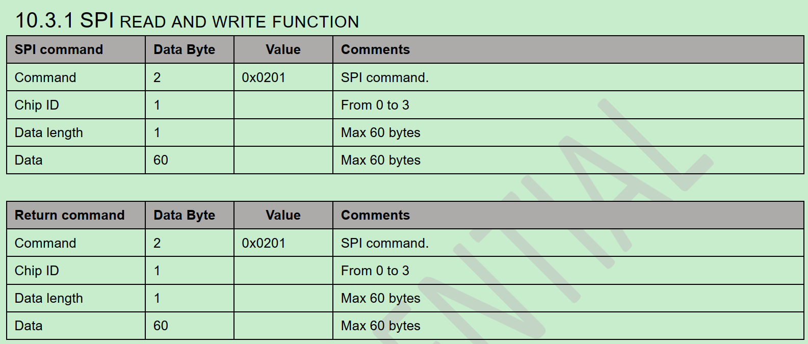
usb_to_spi 前面没有详细分析SPI的传输,此处分析。
o2link spec定义的USB to SPI数据包格式:
SPI数据通信的原理:
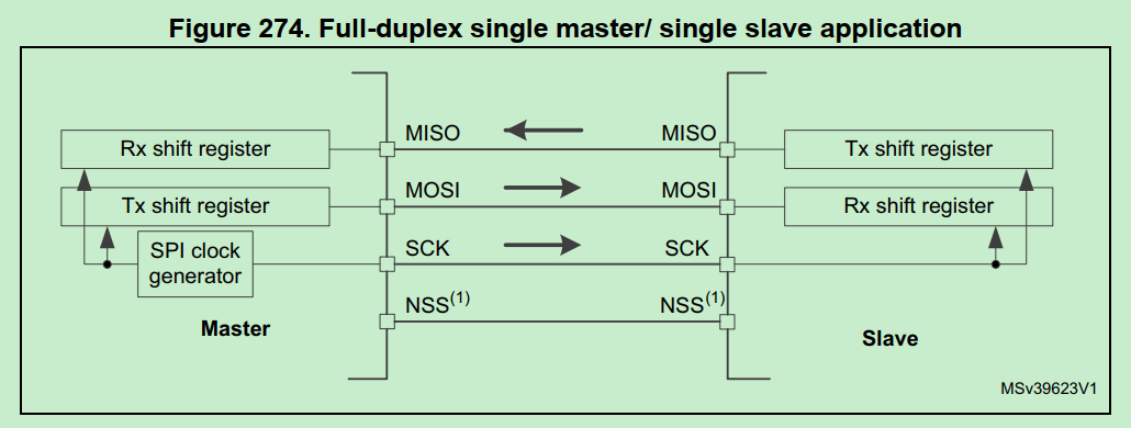
SPI一般设置为全双工双向通信,利用移位register交换master/slave两端的数据register(FIFO)里的数据。
全双工时,SPI不存在单向的发送或单向的接收,数据一定是“交换”的。firmware的关注点是用RX register发数据,还是从Tx register拿数据。
代码分析:
1 2 3 4 5 6 7 8 9 10 11 12 13 14 15 16 17 18 19 20 21 22 23 24 25 26 27 28 29 30 31 32 33 34 35 36 37 38 39 void usb_to_spi_convert(void) { uint8_t recive_buf[SPI_MAX_DATA_NUM] = {0}; uint8_t ret = 0; if (usb_send_buf[SPI_LENGTH_SITE] > 60) { usb_send_buf[0] |= 0x80; usb_send_buf[2] = SPI_INVALID_PARAMETER; usb_send(usb_send_buf, USB_TIMEOUT_TIME); return; } //按o2link spec解析为SPI命令参数和数据,数据内容决定对下层DFE芯片register是读还是写 ret = usb_spi_convert_data(usb_send_buf[SPI_CHIPID_SITE], usb_send_buf[SPI_LENGTH_SITE], &usb_send_buf[SPI_DATA_SITE], recive_buf); if (ret) { usb_send_buf[0] |= 0x80; usb_send_buf[2] = ret; } //按o2link spec解析出返回数据 memcpy(&usb_send_buf[SPI_DATA_SITE], recive_buf, usb_send_buf[SPI_LENGTH_SITE]); usb_send(usb_send_buf, USB_TIMEOUT_TIME); } uint8_t usb_spi_convert_data(uint8_t dev_id,uint8_t data_num,uint8_t * write_buf,uint8_t *read_buf) { uint8_t ret = 0; //拉低CS片选 HAL_GPIO_WritePin(spi_gpio_cs_pins[dev_id].gpio_base,spi_gpio_cs_pins[dev_id].gpio_pin,GPIO_PIN_RESET); //启动SPI传输 ret = HAL_SPI_TransmitReceive(&hspi1, write_buf, read_buf, data_num ,SPI_TIMEOUT_TIME); HAL_GPIO_WritePin(spi_gpio_cs_pins[dev_id].gpio_base,spi_gpio_cs_pins[dev_id].gpio_pin,GPIO_PIN_SET); return ret; }
SPI传输的8bit模式具体内容:
1 2 3 4 5 6 7 8 9 10 11 12 13 14 15 16 17 18 19 20 21 22 23 24 25 26 27 28 29 30 31 32 33 34 35 36 37 38 39 40 41 42 43 44 45 46 47 48 49 50 51 52 53 54 HAL_SPI_TransmitReceive(): hspi->pRxBuffPtr = (uint8_t *)pRxData; //RX buffer的指针 hspi->RxXferCount = Size; hspi->RxXferSize = Size; hspi->pTxBuffPtr = (uint8_t *)pTxData; //TX buffer的指针 hspi->TxXferCount = Size; hspi->TxXferSize = Size; /* Enable SPI peripheral */ __HAL_SPI_ENABLE(hspi); .... /* Transmit and Receive data in 8 Bit mode */ else { .... while ((hspi->TxXferCount > 0U) || (hspi->RxXferCount > 0U)) { /* Check TXE flag */ //SPI_FLAG_TXE: SPI status flag: Tx buffer empty flag, 表示当前TX FIFO数据为空,可能是首次启动还没填数据或上次已传完 if ((__HAL_SPI_GET_FLAG(hspi, SPI_FLAG_TXE)) && (hspi->TxXferCount > 0U) && (txallowed == 1U)) { // DR: SPI data register, 按uint8(byte)填数据 *(__IO uint8_t *)&hspi->Instance->DR = (*hspi->pTxBuffPtr); //更新数据指针(准备下次传输) hspi->pTxBuffPtr++; hspi->TxXferCount--; /* Next Data is a reception (Rx). Tx not allowed */ //处理完TX,下面必须处理RX txallowed = 0U; /* Wait until RXNE flag is reset */ //SPI_FLAG_RXNE: Rx buffer not empty flag, 有收到数据待处理 if ((__HAL_SPI_GET_FLAG(hspi, SPI_FLAG_RXNE)) && (hspi->RxXferCount > 0U)) { //从DR register取数据到RX buffer (*(uint8_t *)hspi->pRxBuffPtr) = *(__IO uint8_t *)&hspi->Instance->DR; hspi->pRxBuffPtr++; hspi->RxXferCount--; /* Next Data is a Transmission (Tx). Tx is allowed */ //处理完RX,下一轮必须处理TX txallowed = 1U; } //超时判断 if ((((HAL_GetTick() - tickstart) >= Timeout) && ((Timeout != HAL_MAX_DELAY))) || (Timeout == 0U)) { errorcode = HAL_TIMEOUT; goto error; } }
TX RX处理的判断标准是读SR register状态:
1 2 3 4 5 6 7 8 9 10 11 12 13 14 15 16 17 /** @brief Check whether the specified SPI flag is set or not. * @param __HANDLE__ specifies the SPI Handle. * This parameter can be SPI where x: 1, 2, or 3 to select the SPI peripheral. * @param __FLAG__ specifies the flag to check. * This parameter can be one of the following values: * @arg SPI_FLAG_RXNE: Receive buffer not empty flag * @arg SPI_FLAG_TXE: Transmit buffer empty flag * @arg SPI_FLAG_CRCERR: CRC error flag * @arg SPI_FLAG_MODF: Mode fault flag * @arg SPI_FLAG_OVR: Overrun flag * @arg SPI_FLAG_BSY: Busy flag * @arg SPI_FLAG_FRE: Frame format error flag * @arg SPI_FLAG_FTLVL: SPI fifo transmission level * @arg SPI_FLAG_FRLVL: SPI fifo reception level * @retval The new state of __FLAG__ (TRUE or FALSE). */ #define __HAL_SPI_GET_FLAG(__HANDLE__, __FLAG__) ((((__HANDLE__)->Instance->SR) & (__FLAG__)) == (__FLAG__))
为什么SPI传输TX,RX是同时又交替的处理数据:
SPI只有主模式和从模式之分,没有读和写的说法,外设的写操作和读操作是同步完成的。若只进行写操作,主机只需忽略接收到的字节;反之,若主机要读取从机的一个字节,就必须发送一个空字节来引发从机的传输。也就是说,你发一个数据必然会收到一个数据;你要收一个数据必须也要先发一个数据。
因此HAL_SPI_TransmitReceive()同时处理RX和TX,和UART的RX/TX单向传输不同。